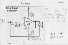
On Cattles' page it has the Input capacitor and resistor pointed to pin 8 yet on Nuuk's page it is pointed to pin 7. Which is the right one
Hi rammsteinme, my diagram also shows the input cap and resistor to pin 8! You may be confused by the connection from pin 7 to ground which I have shown running 'behind' the input resistor in my diagram.
Remember, a resistor has only two connections, not four
") but sorry for any confusion.
but sorry for any confusion.my diagram also shows the input cap and resistor to pin 8!
I'm looking at this diagram http://www.decdun.fsnet.co.uk/gainclonelayout.html and it shows clearly that the input resistor/capacitor going to pin 7. There is a feedback resistor going to pin 8 but that's about the extent of the activity to pin 8. On the document where there is a step-by-step order of assembling part, on part 9 it states this
So it does state that the input resistor/capacitor goes to pin 7. Daniels' gainclone goes from pin8 to a 10K res to a 4.7uf cap and then has a pot before the phono socket for volume control and I assume you skipped that last part.Trim the leadouts of the input resistor and input capacitor so that they fit between the phono socket and pin 7 of the chip. Add sleeving if necessary and solder them together, then to pin 7 of the chip, and lastly to the phono socket.
I may be just an *** and not looking at it correctly at all so please excuse me if I don't see it yet
(which does happen from time to time  )
)
I may be just an *** and not looking at it correctly at all so please excuse me if I don't see it yet (which does happen from time to time )
No, not an *** at all! Just a case of a beginner spotting something that the more experienced didn't
 well done!
I replied to your post late last night and looked at the circuit diagram on the Gainclone page. I didn't realise that you were looking at the component layout diagram which is, as you point out, wrong.
The input resistor should go to pin 8, NOT pin 7 as shown in that diagram. I'll change it as soon as I have time.
Sorry for the confusion.
And in my amp, the pot has been replaced by a resistor to ground as I use mine as monoblocks with an external preamp.
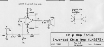
Here's the schematic I'm using. Some components has been changed, but connections are correct.
Hi Peter, 'correct me if I am wrong' seems to be a popular phrase here at the moment
Shouldn't the ground connection from pin 7 go to the the signal ground star rather than the power ground star?
I originally did connect mine directly to the power ground star but found that the sound is better going to the signal ground star!
Hehe... I was pulling my hair out yesterday tracing a circuit of your diagram a couple times to make sure I did it correctly. Glad to know that it was a misprint!
The separate star ground the other thing that I wasn't sure about and wasn't mention on the beginners guide. It was mentioned that you have to do it but not the reason why... I still do not understand the concept because both star grounds will be connected together in the end? (Of course Peter's diagram also confused me slightly because he just took the nearest ground) But now I understand it has to do with distance but what exactly?
Also is there any reason to use the power ground (0v) to the resistor&cap to case then to the power star ground? I was going to hook it up directly from 0v to the power star ground...
Oh and on the larger diagram (http://www.decdun.fsnet.co.uk/gainclonelayout.html) the speaker terminal outs seems to have the wrong colors (if we follow that the red means positive (+) and black is negative (-)) Misprint?
The separate star ground the other thing that I wasn't sure about and wasn't mention on the beginners guide. It was mentioned that you have to do it but not the reason why... I still do not understand the concept because both star grounds will be connected together in the end? (Of course Peter's diagram also confused me slightly because he just took the nearest ground
) But now I understand it has to do with distance but what exactly?Also is there any reason to use the power ground (0v) to the resistor&cap to case then to the power star ground? I was going to hook it up directly from 0v to the power star ground...
Oh and on the larger diagram (http://www.decdun.fsnet.co.uk/gainclonelayout.html) the speaker terminal outs seems to have the wrong colors (if we follow that the red means positive (+) and black is negative (-)) Misprint?
Ok, the reason for separate star grounds for signals and power as simply as I can explain it!
Let's use the water analogy! We want the signal as 'pure' as possible and we know the power is 'polluted'. So we want to keep the two separate as best we can.
So the idea is that the returns to the power ground star are returned to the main ground star in the PSU without getting into the signal ground star. Still with me?
In theory, the wire going from the power ground star to the main ground star should be thicker than the wire connecting the signal ground star to it. Thicker wire, less resistance, so the 'pollution' flows to the main ground star and not into the signal ground star where it could affect the signal.
http://www.national.com/ds.cgi/LM/LM3875.pdf
The single point ground principle is explained in the chip data sheet. Basically you should not have big currents flowing in the signal ground, because ground wire has some small resistance that causes small voltage that is seen as an input signal. U=RI.
It is also good practice to separate speaker and power supply ground the same way.
here is my attempt,
any wire will have resistance, capacitance, etc. so think of a wire as a resistor in its simplest form.
If different sections of the amp are grounded differently and linked with those wire/resistors, as current flows through those wires, it will produce little voltage that can be picked up by, for example, the input stage and amplified later one, causing obiviously problems.
To ground all sections of the amp together will eliminate that problem. alternatively, you can use really large wires (small resistors) to link those grounding points together.

Nuuk I noticed the new diagram but did you correct the step-by-step guide as well (part #9) that says to point to pin 7?
No I didn't
It will be done today. Thanks again for pointing out these mistakes; both from me and those who come along after you.good attempt
Absolutely correct.
You should not have differences in potential.
Ground wires should be thick, for the grounds to flow fast.
Less noise.
That's why on some PCBs you see large tracks for the ground, almost all the empty spaces of the PCB are occupied with the ground tracks.
millwood said:here is my attempt,
any wire will have resistance, capacitance, etc. so think of a wire as a resistor in its simplest form.
If different sections of the amp are grounded differently and linked with those wire/resistors, as current flows through those wires, it will produce little voltage that can be picked up by, for example, the input stage and amplified later one, causing obiviously problems.
To ground all sections of the amp together will eliminate that problem. alternatively, you can use really large wires (small resistors) to link those grounding points together.
Absolutely correct.
You should not have differences in potential.
Ground wires should be thick, for the grounds to flow fast.
Less noise.
That's why on some PCBs you see large tracks for the ground, almost all the empty spaces of the PCB are occupied with the ground tracks.
loading any page on www.decdun.fsnet.co.uk/ crashes safari
What is safari? If it's a browser, I'm not sure why DD would cause any crashes. Apart from a little javascript code, it is just CSS/HTML!
its a browser. i sent in a bug report to Apple cos no javascript should be able to crash a browser. you know?
I agree. FYI I have had no other reports of my site crashing a browser. I'd be interested to hear what Apple have to say.
- Status
- This old topic is closed. If you want to reopen this topic, contact a moderator using the "Report Post" button.
- Home
- Amplifiers
- Chip Amps
- Beginner's Gainclone guide