That njm2043 has good specs 6v/us 14mhz GBW. the lm4562 has lower distortion and could sound better but is more likely not to perceive the difference on well designed equipment like this. supply voltage should be lowered which will lessen dynamic range somewhat. The electrolytic caps should be replaced along with any resistors that appear to get hot.
Many thanks for the replies.
MY bad, the voltage between pins 4 and 8 is 34.5 volts making it effectively plus minus 17.5 volts, I hadn't noticed at first there is a resistor in the rails on the way to the power pins of the opamp.
As for the caps, they look like originals since they look the same as what I see in pics on the web of the inside of other 1130's, I dont have this unit from new.
There are a number of yellow disk ceramics and some glossy dark green polyester films caps, all visually look ok.
The dielectrics are a small number of YEC capacitors and the rest are mainly bright blue with a symbol on them, namely an A inside a circle, there is no other designation on them, I cant find anything about these on the web, I'm wondering are these dielectrics nothing special. so unless you guys tell me these are some sort of super special dielectrics, then I'll be doing up a list on mouser for replacements.
I wouldn't replace any other caps apart from the electrolytics.
You might find there is a Zener diode wired to ground on each of those supply resistors that operates as a shunt stabilizing element... which is pretty standard and means the supply of -/+17.5 volts can be used safely with most 'audio' opamps.
You might find there is a Zener diode wired to ground on each of those supply resistors that operates as a shunt stabilizing element... which is pretty standard and means the supply of -/+17.5 volts can be used safely with most 'audio' opamps.
I am very interested on the internal circuits of the LME49713, LME49710 and LM4562.Hi DIY Audio Group and Johnego,
I have been doing this "audio stuff" a very long time and worked closely with great analog circuit engineers like Bob Pease at National Semi. I will tell you the LME49713 is the best sounding opamp we ever created on the very special LME high voltage process that is gone now. We did extensive listening sessions comparing VFB and CFB opamps and for most applications we preferred the LME CFB's (LME49713HA) with the exception sometimes being for +/- DAC outputs where the identical +/- inputs on the VFB opamps present identical loads to the DAC's. The +/- inputs on a CFB opamp are different input circuits.
Anyway we designed the LME49713HA CFB opamps to exceed the AD811 specs and made some significant changes to optimize it for audio (rather than video) but the bandwidth is still very high (which is a good thing for a lot of reasons) and thus requires careful PC layout to prevent oscillations. The AD811 was based on the AD9610 metal can mil spec opamps and one of the best measuring and sounding opamps ever...also super expensive and impossible to find. I still have a few for personal projects.
We attempted to do our critical listening tests (after all the measurement tests) single and double blind but there is always room for error/disagreement in all listening results.
Just wanted everyone on this forum to think/try VFB and CFB (voltage feed back vs current feedback) opamps in their new designs. I mentioned the older AD811 ADI CFB parts because the last I heard the LME high voltage process was shut down by TI.
Best “Retired” Audio Regards Everyone,
audioman54
In the associated datasheets I don't find it - go to
http://80.93.56.75/pdf/0/5/5/2/1/05521640.pdf
https://www.pken.net/ish_mm/datasheet/ns/lme49710.pdf
and
http://www.ti.com/lit/ds/symlink/lm4562.pdf
- not even a simplified circuit.
What is the reason therefore ?
Which of the under
http://www.nanovolt.ch/resources/ic_opamps/pdf/opamp_distortion.pdf
mentioned topologies corresponds to the internal circuit of these three mentioned types ?
Thank you very much for your advices.
Which of the under
http://www.nanovolt.ch/resources/ic_opamps/pdf/opamp_distortion.pdf
mentioned topologies corresponds to the internal circuit of these three mentioned types ?
Thank you very much for your advices.
Probably none fit exactly, BTW most of the stuff in your quoted post is fantasy especially things done for "audio" to IC op-amps.
I already thought so. In general - when I read "special made for High-End Audio" on IC's, capacitors PCB's and cables or resistors, one can almost be sure that one have not made a really good choice in order to get perfect sonic results.Probably none fit exactly, BTW most of the stuff in your quoted post is fantasy especially things done for "audio" to IC op-amps.
A good example are OPA's made for video application. Sound quality is for a lot of user's and designer's better than from typicall OPA's special made for audio like NE5532. Tim de Paravicini (Musical Fidelity P170) are a good example - go to post #67 under
Musical Fidelity P170 Power Amp
and page 15 under
http://www.ti.com/lit/ds/symlink/lm318-n.pdf
any advices ?Most of the internal structures, which I note by opamps are this:
1) one voltage gain stage (mostly folded cascode) + buffer - mainly used in video op-amps
2) two voltage gain stages (LTP + VAS with internal and/or external Cdom) + buffer - mainly used in typical audio op-amps
(AD797 and OPA604/2604 are examples of exceptions - because the simplified schematics looks a lot like those from video op amps).
Concerning the sonic quality I note, that most op-amps with one internal voltage gain stage provides better results than such with two gain stages, as long the non inverted mode is in use (both RIAA and line stages applications).
But what happens at listening tests by using inverting mode topologies between this mentioned kinds of topologies (e.g. NE5534 vs. AD829 resp. dual versions NE5532 vs. AD826)? - go for example to the circuit diagrams in post from Mon Dec 16, 2013 2:14 pm under
Shunt feedback in phono preamplifiers : new topics on this forum
Thank you for advices.
And a second question: where are to filed the LME-Series from TI - are there one or two voltage gain stages internal in use - ? go to
Where are intern. schematic of LME49710 LME49720 and LM4562 (LM 4562 LME 49710 49720) - Page 2 - diyAudio
Last edited:
I already thought so. In general - when I read "special made for High-End Audio" on IC's, capacitors PCB's and cables or resistors, one can almost be sure that one have not made a really good choice in order to get perfect sonic results.
any advices ?
Not sure I can help here, some say the inverting connection has no common mode errors so that is the difference. The 797 has one stage + buffer BTW, two stage amplifiers usually show rising or peaking noise at high frequencies which matters in some applications beyond audio.
OPA1662AIDR any experiences?
I have a box of OPA1662 on it's way from Digikey.
Anyone try these out?
I am going to try them in my pre/pro (Emotiva LMC-1) in my H.T. system, they will be replacing TLO72. They are surface mount which will be fun.
So going from a fet input device to a bipolar with much higher bandwidth.
Also have some real OPA602AM yes the TO99 gold lead package I know these are real because I bought them from Newark electronics back when they were a current product. Just never found a use for them being a single device package.
Might use them in a Lampizator greendac board that I have kicking around.
thoughts?
Inverting Buffer
I'm trying to make an inverting buffer to pair a pre-amp to headphones and hoping for some recommendations for a suitable op-amp. (Sorry, I've only just started to dip my toes into chips!)
Input impedance is 140ohm, headphones are 32ohm upwards.
I have 24v and 9v single supply available.
The OPA1688 looks like it might be suitable?
And is this the appropriate scheme:

(The pre-amp is capable of driving the headphones already but there is a single inverting stage that makes it sound not-so-nice)
I'm trying to make an inverting buffer to pair a pre-amp to headphones and hoping for some recommendations for a suitable op-amp. (Sorry, I've only just started to dip my toes into chips!)
Input impedance is 140ohm, headphones are 32ohm upwards.
I have 24v and 9v single supply available.
The OPA1688 looks like it might be suitable?
And is this the appropriate scheme:
(The pre-amp is capable of driving the headphones already but there is a single inverting stage that makes it sound not-so-nice)
Last edited:
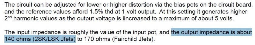
Input impedance is 140ohm
Weird number. How did you come up with it?
Not that the circuit shown has either such ridiculously low input impedance or is inverting.
Is this what you are looking for?I'm trying to make an inverting buffer to pair a pre-amp to headphones and hoping for some recommendations for a suitable op-amp. (Sorry, I've only just started to dip my toes into chips!)
Attachments

Weird number. How did you come up with it?
Not that the circuit shown has either such ridiculously low input impedance or is inverting.
That number came from the application note by Nelson Pass.
Is this one better:
Is this what you are looking for?
Thanks, that looks like it could work.
Am I right that the gain for that one is A = -47k/12k = -3.91?
Would I need to alter the values to match the source impedance?
Attachments
That looks like a cracking op amp for the job. It's the first time I have come across it so I don't know if it's the zenith for a headphone amp (having never done one) but you could certainly do (a lot) worse.
No, that's not the arrangement for an inverter. The usual setup is the -ve input being used with a series resistor and (for a gain of 1) the same resistor in the feedback loop. You then take the +ve to Gnd through a resistor or directly. Look at the datasheet for this (I have only skimmed it) but don't let the feedback resistor get so low that it's drawing too much current. There is often some advice in the datasheet on what the chip likes best but in general you don't want to be heating up the feedback resistor. You can also use the feedback resistor as a volume control if you put a pot in its place.
You will also need to bias the op amp to 1/2 Vcc, which also means you will need a capacitor on the input and output. How you drop the 4.5V or 12V onto the input is up to you but if you use a potential divider then half of the ripple on the supply will get onto the signal path. It's a dreadful way of doing it but plenty of people have in the past.
You would probably be best to do this inside the pre- amp where you will probably have split supplies which are already regulated. You also might consider driving the headphones in bridged mode. Some people don't recommend this (Bruno from Hypex for instance) but I can't remember the reasons why. The other thing you could do is just rewire the opamp that's in there already to being a follower rather than an inverter. I have to say that I'd be quite surprised if you can tell the difference between an inverted signal and one in absolute phase, especially as the inverting inputs usually have much lower distortion (though it seems not on this OPA1688). Since the OPA1688 should be as near as dammit transparent in a decent embodiment, I would really wonder if you will get any improvement at all by tacking one on the output of the pre-.
The other thing you might want to do, which again will be much less work, is replacing the existing op amp with one that is pin compatible. If what's in there at the moment is a dual SOIC then you're good to go with the 1688.
Thanks for the detailed reply Christian.
The pre-amp has a triode so I am unfortunately unable to plug-and-play other chips. Single supply of +9v or +24v only available also. But I could always look at a 24v to +12v/-12v converter to avoid some of the ripple and the caps.
I wonder how the OPA1688 compares sound-wise to say the LME49720?
The pre-amp has a triode so I am unfortunately unable to plug-and-play other chips. Single supply of +9v or +24v only available also. But I could always look at a 24v to +12v/-12v converter to avoid some of the ripple and the caps.
I wonder how the OPA1688 compares sound-wise to say the LME49720?
49720 will be good only for 600 ohms headphones...opa1688 is not too expensive but i hate its footprint...not the best for diy.
If you have a triode trying to drive the headphone amp you need a unity gain buffer then, cause the inverter impedance is done by the input resistor paralleled with the potentiometer and valves are't very good at driving low impedances.Ecc88 will drive a 10k..20k potentiometer by itself with no problem but lower values might cause a problem.
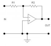
The headphones amp schematic is working in some of the best Yamaha cassette players and monitoring the line input from a cd player made me realize that this is a very good headphones amp.Now i would recommend something even more interesting as i'm going to build this thing myself after having a chat with a friend who has the Technics slp990. As you see, they both use very low value potentiometers , 1k in the Technics which has a unity gain buffer for that purpose.
Both used njm4556s (sa) which was a special version of njm4556, but the usual 4556D through hole version can do a very good job too.
If you have a triode trying to drive the headphone amp you need a unity gain buffer then, cause the inverter impedance is done by the input resistor paralleled with the potentiometer and valves are't very good at driving low impedances.Ecc88 will drive a 10k..20k potentiometer by itself with no problem but lower values might cause a problem.
The headphones amp schematic is working in some of the best Yamaha cassette players and monitoring the line input from a cd player made me realize that this is a very good headphones amp.Now i would recommend something even more interesting as i'm going to build this thing myself after having a chat with a friend who has the Technics slp990. As you see, they both use very low value potentiometers , 1k in the Technics which has a unity gain buffer for that purpose.
Both used njm4556s (sa) which was a special version of njm4556, but the usual 4556D through hole version can do a very good job too.
Attachments
Last edited:
Thanks for the detailed reply Christian.
The pre-amp has a triode so I am unfortunately unable to plug-and-play other chips. Single supply of +9v or +24v only available also. But I could always look at a 24v to +12v/-12v converter to avoid some of the ripple and the caps.
I wonder how the OPA1688 compares sound-wise to say the LME49720?
LME49720 will do only an OK job for easy loads. OPA1622 is the best alternative, but it is not easy to solder if you don't have experience with surface mount devices.
If you are putting a potentiometer in front of it, then look at OPA1656 or use a FET input op-amp like OPA1641/2 and a BUF634A in the feedback loop.
Thanks for the tips.
I'll probably grab some OPA1688 and some njm4556 and make a couple of boards and see which works best on the bench.
The triode is buffered by a pair of 2SK170 jfets and I am looking to put that signal output through as simple an inverter as possible. There is already volume control at the front end via a 50k pot, although there is a slight temptation to add a gain pot.. but one step at a time!
- Home
- Amplifiers
- Chip Amps
- The best sounding audio integrated opamps