The OPA228 doesn't want to see capacitive loads on its output when set at unity gain - be warned. It'd be a better idea to use the OPA227 as "final buffer", except that the OPA228 sounds somewhat better..
Why not OPA228 just after the DAC, and something else (maybe AD797, provided it works well) on the other stage? This would have more logic..")
Why not OPA228 just after the DAC, and something else (maybe AD797, provided it works well) on the other stage? This would have more logic..
Have you actually listened to all that? No offense intended but...what an awful lot of theoretical speculation for something so immediate to evaluate such as audio.Still following this...
One for Leeperry
The OPA2604... using the "test circuit" from Audio GD ? have I got the name right.
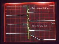
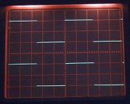
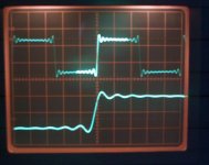
Just some quick scope shots... and just to explain what you are looking at,
the top trace is the input, the one below is the falling edge highlighted, next is the output and again the falling edge highlighted and expanded so you can see more clearly. My generator produces much faster rise/fall times than the one they use in the test
Output is 10volts pk pk (scope adjusted to fit four traces on) and frequency is 100khz.
1. Shows the test circuit from your link. н¨ÍøÒ³ 1
2. Shows same but with the input signal slew rate limited.
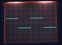
3. Shows 15pf comp to the OPA2604
4. Shows 22pf comp to the OPA2604
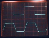
5. Shows why it is important to implement correctly. This shows an NE5532 in the same circuit. A 1k input resistor has been added in series to the input 100 ohm. What you are seeing here is the generator signal (top) and the signal as distorted by the input circuitry of the NE5532 (this is NOT the output you are looking at but the signal on the 100 ohm.
Frequency here lower... 10khz
BTW I don't see how a square wave would be a good indicator of distortion (in audio) or lack of it. Have you tried comparing sine waves??
meaning hell might break loose?The OPA228 doesn't want to see capacitive loads on its output when set at unity gain - be warned.

Well...it would simply be more likely to oscillate than in the former stage, audibly or not... depending on the series output resistance mainly.meaning hell might break loose?
Anyway I think (differently from majkel) that the OPA227/2227P is worth trying too. Lately I saw that a expensive "Simaudio Moon" integrated amp uses the OPA2227 as an output buffer in its (expensive) phono stage board.
thanks Mooly! but this is going over way my head I'm afraid..
anyway, I'll prolly roll the 2*AD797BN final buffer for OPA228/227P for the hell of it
The scope trace's simply show voltage on the vertical scale, and time on the horizontal.
If you look at the input waveform here you can see that the generator signal switches abrubtly as shown by the fast "edges" to the signal. The trace below is with the time scale expanded to show it in detail.
The bottom two traces are the output of the opamp with the lower expanded in the same way.
You can see that the output "slews or changes at a linear rate determined by the actual device in question.
In other words the output can't follow the fast rise and fall time of the generator. Look at the overshoot too on the leading edge (not highlighted)
The vertical green lines show the "time" the input signal takes to fall (1st to 2nd line and the corresponding output of the opamp 1st to 3rd)
By making the input signal change at a slower rate the opamp output can now follow the rate of change... as shown in the other shots.
Get a rate of change that the opamp can cope with and compensate accordingly and you can make the output and input seem identical... as in the audio GD thing.
Attachments
That they have a good "scope fidelity to square waves" doesn't mean that the Audio-GD opamps sound perfect unfortunately...as in the audio GD thing.
Have you actually listened to all that? No offense intended but...what an awful lot of theoretical speculation for something so immediate to evaluate such as audio.
BTW I don't see how a square wave would be a good indicator of distortion (in audio) or lack of it. Have you tried comparing sine waves??
Non taken If we compared sine waves you would probably be happy with a 741
Square wave testing highlights many problems that would never show on sine testing. Over/undershoot into a capacitive load would not show for one. That shot I showed of the NE5532 input another. Square wave testing is a valuable tool.
I agree that all the tests like this still don't determine "how" a device may sound but it goes a long toward setting a base standard and being able to compare like with like and making sure you are using devices in a correct way.
In a DAC filter stage there's a lot of low-pass filtering capacitance around the opamps, which I reckon helps to stabilize the opamps...
As every opamp I've tried (even those made for audio yet not unity gain stable, like LT1115 and LT1028) seemed completely at home in my DAC(s), with the own sonic signatures of each emerging without issues Call it 6th sense
As I mentioned before, there were indeed a few that didn't work properly (in the Super Pro), but that was apparent in a couple of seconds, no more...: OPA2822, THS4031, EL2227, EL2228, OPA2613, and AD826 (this wasn't obvious...it saturated on certain music peaks). For the rest... I don't buy it that "compare like with like and making sure you are using devices in a correct way." was not what I've been doing all the time.
Also in case with like with like you meant FET and bipolar... the opamps see a low input impedance in my DAC(s) so this is a non issue.
Ah well... did you know (I'm sure you did) that sound is made of waves that are muuuuch more sine than square? What do you care if (in a circuit different than the real thing) the corner of a square wave is a bit rounded on the scope, when you already know that a digital signal can't ever slew faster than about .7 V/uS? Please tell me if that slew rate would be sufficient for producing a square wave of 2V RMS amplitude at audio frequencies, as I don't know the maths
As every opamp I've tried (even those made for audio yet not unity gain stable, like LT1115 and LT1028) seemed completely at home in my DAC(s), with the own sonic signatures of each emerging without issues
Call it 6th sense As I mentioned before, there were indeed a few that didn't work properly (in the Super Pro), but that was apparent in a couple of seconds, no more...: OPA2822, THS4031, EL2227, EL2228, OPA2613, and AD826 (this wasn't obvious...it saturated on certain music peaks). For the rest... I don't buy it that "compare like with like and making sure you are using devices in a correct way." was not what I've been doing all the time.
Also in case with like with like you meant FET and bipolar... the opamps see a low input impedance in my DAC(s) so this is a non issue.
Ah well... did you know (I'm sure you did) that sound is made of waves that are muuuuch more sine than square? What do you care if (in a circuit different than the real thing) the corner of a square wave is a bit rounded on the scope, when you already know that a digital signal can't ever slew faster than about .7 V/uS? Please tell me if that slew rate would be sufficient for producing a square wave of 2V RMS amplitude at audio frequencies, as I don't know the maths
Last edited:
BTW, a possible exception was the AD797ANZ -- this I suspect I may not have heard at its best (in the SVDAC05). Maybe I'm wrong. Anyhow, this particular opamp is known to be pretty unique (since it's a decompensated high-gain single stage opamp) with frequent stability problems...
BTW I don't see how a square wave would be a good indicator of distortion (in audio) or lack of it. Have you tried comparing sine waves??
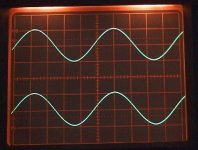
Hi Andrea,
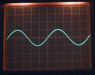
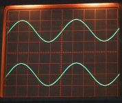
Here are some shots of sinewave testing the NE5532 in the same test circuit. The ouput was 10 volts pk pk.
The "single" trace is input and output overlaid... with the squarewave there was no point
Attachments
Last edited:
Interesting... the UA741 is underrated, I say!!!
Anyway, there's really light years of distance between a scope trace of any given wave at any given frequency, and how the thing will actually sound...
I still have no doubts that our hearing (even with its imperfections) is a faaaaaaaaaaaaar more sophisticated measurement tool than any instrument man has conceived yet...
I hope that goes a little way to showing why square wave testing is so useful.
The frequencies used (100k) and a 10 volt swing are a little unrealistic, but... it's very useful to do.
Can you see how when the 5532 "slews" at that linear rate (when it can't follow the rate of change of input) that any other "detail" during that time frame is lost.
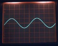
Again, at the frequencies used and for audio it's a little academic anyway, and just to show what I mean here is 1 khz from a CD player (did I post this before), that even the 741 would handle OK at low levels.
But to sum up, squarewave testing is extremely useful and as for distortion, it would have to be pretty bad to show on a scope... you just don't see it.
The frequencies used (100k) and a 10 volt swing are a little unrealistic, but... it's very useful to do.
Can you see how when the 5532 "slews" at that linear rate (when it can't follow the rate of change of input) that any other "detail" during that time frame is lost.
Again, at the frequencies used and for audio it's a little academic anyway, and just to show what I mean here is 1 khz from a CD player (did I post this before
), that even the 741 would handle OK at low levels.But to sum up, squarewave testing is extremely useful and as for distortion, it would have to be pretty bad to show on a scope... you just don't see it.
Attachments
Interesting... the UA741 is underrated, I say!!!
Anyway, there's really light years of distance between a scope trace of any given wave at any given frequency, and how the thing will actually sound...
I still have no doubts that our hearing (even with its imperfections) is a faaaaaaaaaaaaar more sophisticated measurement tool than any instrument man has conceived yet...
Of course... you can't tell how something will sound from measurement alone, BUT, it's an essential part of the process.
I saw similar pictures of square waves output by CD players many times in an Italian audio magazine... yup, CD makes square waves look like that. Alright... provided that it sounds good.I hope that goes a little way to showing why square wave testing is so useful.
The frequencies used (100k) and a 10 volt swing are a little unrealistic, but... it's very useful to do.
Can you see how when the 5532 "slews" at that linear rate (when it can't follow the rate of change of input) that any other "detail" during that time frame is lost.
Again, at the frequencies used and for audio it's a little academic anyway, and just to show what I mean here is 1 khz from a CD player (did I post this before
But to sum up, squarewave testing is extremely useful and as for distortion, it would have to be pretty bad to show on a scope... you just don't see it.
Of course... you can't tell how something will sound from measurement alone, BUT, it's an essential part of the process.
Depends on how evolved your aesthetic perception & your inner grasp of 'truth' happens to be
And, depends on the application... in a DAC output stage such as mine, I guess it's not essential at all...
Last edited:
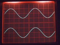
I saw similar pictures of square waves output by CD players many times in an Italian audio magazine... yup, CD makes square waves look like that. Alright... provided that it sounds good.
They look like that for two reasons, the absolute upper limit of 20khz... which means that the harmonics that make up the squarewave are lost, and the action of the filters that cause "ringing"
Put a 6khz squarewave (analog input signal) into a ADC/DAC convertor and you will see a triangular wave emerge because the harmonics are lost.
So designing for perfect squarewave response at 100k is academic when CD is the source.
IMO it is better to sensibly tailor the response to gentle roll off outside the audio band (well outside of course) and I find that gives the best results very often.
Edit... I am refering to a typical ADC/DAC as in domestic equipment.
- Home
- Amplifiers
- Chip Amps
- The best sounding audio integrated opamps