I am planning to build 5 channel + 2 channel bridge with power supply on single PCB. Please post any PCB with clear & big picture. Building single gainclone is very easy but multiple gainclone is complex.
My first try would be TDA2030 because it is cheap IC. Then 2050 & 3886.
Specially, I am worried about wiring management RC GROUND, POWER GROUND etc.,
Regards.
My first try would be TDA2030 because it is cheap IC. Then 2050 & 3886.
Specially, I am worried about wiring management RC GROUND, POWER GROUND etc.,
Regards.
You want ALL of that on one single PCB, am I right? Are you going to Design the PCBs by yourself?
If yes, you could habe a look hat my thread in which you can learn much about grounding I think: http://www.diyaudio.com/forums/chip-amps/152528-lm3886-layout-ok.html
If yes, you could habe a look hat my thread in which you can learn much about grounding I think: http://www.diyaudio.com/forums/chip-amps/152528-lm3886-layout-ok.html
You are right this is extreemly complex to maintain a unconditionally stable desing. I found it possible to share the power supply rails with good decoupling local to the amps. However a seperate ground return from each of the speaker loads was required to the bulk decoupling capacitor star point and this had to be kept close to the power output track to the speaker. An output inductor bypassed with a 10R resistor was required to isolate the amplifers from capacitance in the cables and a Zobel network with a seperate ground return required for each amplifer. It required a 4 layer PCB to achieve this in a small space for a comercial design. You may be able to do it on a two layer PCB if you are preapred to use lots of space. Best of luck Andrew
Thanks
@Maxxtr0 : Your LM3886 layout is good and usefull. I have already tried 5 mono amp. It's sound good individually or stereo configuration.
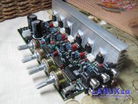
@gfiandy : Thousand words v/s single picture. I found thread "Giga Amp 5.1 channel" by myanmar (please find attached picture) is good but not very clear. Exactly I need this but require big and clear picture to understand. Yet, your post # 4 is usefull to me.
Thank you
@Maxxtr0 : Your LM3886 layout is good and usefull. I have already tried 5 mono amp. It's sound good individually or stereo configuration.
@gfiandy : Thousand words v/s single picture. I found thread "Giga Amp 5.1 channel" by myanmar (please find attached picture) is good but not very clear. Exactly I need this but require big and clear picture to understand. Yet, your post # 4 is usefull to me.
Thank you
Attachments
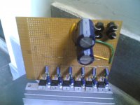
6 channel on single PCB
At last, I build 6 channel on single PCB with TDA2030 it was my dream. Good bass and good loudness but not sufficient. Everything is fine but MID & HIGH frequencies are not good. I like MID-HIGH frequencies soft & delicate. Bass should be soft but strong.
Overall ambience, quality sound. Sorry I can not describe but can you improve my schematic ?
Zobel does not make any good difference to me. But if you advise I can add.
Thank you
Regards.
Attachments
Hi, You could try fiddling arround with the supply decoupling but to be honist I suspect the problem is the chip amps. The TDA2030 is a fine low cost audio amp, but if you want something that is a bit better I would try the LM1875. The circuit is very similar however its performance is much better.
If you want some advice on the layout we will need to see both sides of the PCB. However it looks like you have daisy chained the supplies and ground. If this is the case then a star arrangement will probably sound better.
Regards,
Andrew
If you want some advice on the layout we will need to see both sides of the PCB. However it looks like you have daisy chained the supplies and ground. If this is the case then a star arrangement will probably sound better.
Regards,
Andrew
@gfiandy
Thank you.
Attached picture may help you to advise good layout. In my first attached picture you may find 1R+0.1uf with this sound improved little.
Today, I found that Diode (6Amp) becomes very hot. What is the reason ? But still I listen the Amp for 1 hour I did not find any problem with system & it's sound.
Another major thing is ON/OFF power switching noise. When I tried mono amp it was not.
Please find attached picture for layout.
Thanks & Regards.
Attachments
The 6A diode is probably hot due to the combined current use of all 6 parts.
You can work this out in standby from the data sheets. Find the standby current for the part, 40mA in this case, then multiply it by the forward voltage of the diode (probably about 0.8V) it will tell you the power being dissipated.
I make this 40mA x 6 = 240mA, 240mA x 0.8 = 192mW .
I looked up a standard 6A diodes thermal resistance for a P600 case (which yours looks like) and it is 20 degC per W. So I would expect to see a temperature rise of 0.192 x 20 = 3.84 degC divided by the number of diodes per rail which is 2 so only about 2 degC in standby. If it is alot more than this then one of your amplifers is probably unstable which causes them to use much more current. If this is the case try improving decoupling and reducing the ground return impedance.
When in use all the current for all 6 amplifers flows though the rectifier diodes so much more heating will occur. The diodes are typically OK upto a case temperature of about 120 degC. It will burn you instantly at this temperature so if you can touch the diode at all it is probably OK. Obviously be very careful touching the diodes for the above reason.
On / off noise is probably caused by interaction between power rails. For low on / off noise you need the power rails to come up and go down very symetrically. If the amp draws slightly more off one rail than the other this would be 6 x worse as you increase the number of ampliers. This can be very dificult to resolve without isolating the power supplies for each amplifer; probably the only way to do it is to use a mute relay at the output or change to an amplifer that has a built in mute. (Even these sometimes make some noise)
Regards,
Andrew
Last edited:
If you're looking at any significant power level, I would highly recommend hybrid digital or at least analog with dynamic supply voltage. The reduction in heat dissipation is well worth it.
Note that the power requirements for 5.1 are not the same for all channels. The subwoofer needs the most, followed by the front speakers and finally the rear speakers. That is something to keep in mind during design. You may also want to make it modular in case you want to use them separately in the future. (For example, the subwoofer amplifier, front amplifier, and rear amplifier can be made as separate units.)
Note that the power requirements for 5.1 are not the same for all channels. The subwoofer needs the most, followed by the front speakers and finally the rear speakers. That is something to keep in mind during design. You may also want to make it modular in case you want to use them separately in the future. (For example, the subwoofer amplifier, front amplifier, and rear amplifier can be made as separate units.)
probably the only way to do it is to use a mute relay at the output or change to an amplifer that has a built in mute. (Even these sometimes make some noise)
TDA2030A has no mute pin. I am not confident I will be able to build mute relay at the output for each 6 channels.
Today's modifications & observations.
1) I have added 0.1uf x 4 ceramic caps at rectifier diode. And 0.1 each at speaker out connector. Improvement is clear tone & good mid-high. 8 Ohms speaker is the best option for mid-high. 4 Ohms is suitable for BASS.
2) My source is DVD Player. If I power on amp only (not DVD-P ) there is not on/off thump. Thump comes when I power on DVD-P. ( It was not with mono-tda2030 amp )
3) I read here chipamp forum that source ground wire should be THIN & power ground should be THICK. But I did not find any difference.
4) I am using 5A 12-0-12 transformer ( 120VA is that right ?) smoothing caps are 4700uf 25V. Is that the problem ? I have seen some circuits on the net they use 2.5A 12-0-12 transformer smoothing caps are 3300uf 25v.
PROBLEM IS STILL PENDING. DIODE HOT & ON/OFF THUMP.
@gfiandy : What exactly I should do. Should I add components OR change something in layout ? ( Sorry I am not electronics man to understand theory. )
@star882 : As you advised, prior to this (tda2030) I build tda2050 modular type. I could not build right-way & tda2050 system is now in dust-been.
MY OPINION : I read, many diy'er opinion about tda2030A (yes, it's not high quality sound). But I found it is very-very good for the money I invest. Only some trouble-shooting is needed.
Thank you gfiandy, star882 & Regards.
Hi,
Are the diodes hot when the amp is on but not being used.
If yes - amp is unstable. Try adding 10uF caps very close to power pins on amplifer and re test.
No - Heat is due to power drawn by amplifers.
Do diodes get to hot to touch
Yes - use bigger diodes (preferably a bridge rectifier that can be bolted to a heat sink)
or split power supply so sub woofer is driven seperately from other amplifers
No - Diodes are ok stop worring about them getting a bit hot.
Powe on thump. With more information it sounds like you are getting a charge pulse from the DVD player on the input coupling capacitor.
Try between 22K to 47K resistor from input side of coupling cap to the input ground on each channel.
(the lower the resistance the less thump you will probably get you could go as low as 10K with no problem if required)
Regards,
Andrew
Last edited:
I will check today.Are the diodes hot when the amp is on but not being used
Please find attached picture I think, I have already used 22k resistor.Try between 22K to 47K resistor from input side of coupling cap to the input ground on each channel.
(the lower the resistance the less thump you will probably get you could go as low as 10K with no problem if required)
Today's modifications & observations
1) (As per attached picture ) From Top side, first two channels bridged for sub. From bottom, first two channel used for front Left & Right speakers. Front speakers has good thump (moving speaker back_forward two or three times with sound) compare to bridged sub.
Thanks & Regards.
Attachments
Are the diodes hot when the amp is on but not being used.
If yes - amp is unstable. Try adding 10uF caps very close to power pins on amplifer and re test.
Yes, diodes hot when the amp is ON & volume MUTE by DVD Player. How exactly 10uF caps very close to power pins. i.e between Pin 3 & 5 or how ?
The 22k is on the wrong side of the input cap to prevent the problem I am describing. You may need both.
You mean as per attached picture ?
Attachments
22K resistor or 10K resistor does not work for me. I use as per attached picture in post # 18
I have used 2.2uF electrolytic cap as input DC Decoupling (refer picture post # 16) positive side at ic pin. As per datasheet negative side at ic pin. Does it make any difference ? I am using split power supply.
I have used 2.2uF electrolytic cap as input DC Decoupling (refer picture post # 16) positive side at ic pin. As per datasheet negative side at ic pin. Does it make any difference ? I am using split power supply.
- Status
- This old topic is closed. If you want to reopen this topic, contact a moderator using the "Report Post" button.
- Home
- Amplifiers
- Chip Amps
- 5 + 2 (bridge) channel gainclone