I am planning to use some my LME498xx driver boards to build a headphone amp. Output devices will be MJE15030/31 since I have some of them.
Before I start doing the output stage. Let me try to use 49810 to direct drive my AKG K240. And see how does the chip perform at low rails < +/-20 V.
Before I start doing the output stage. Let me try to use 49810 to direct drive my AKG K240. And see how does the chip perform at low rails < +/-20 V.
Why not try using LM4562 and output buffer like BUF634 or better HA-5002?
Just want see if this is another good application for 498xx.
I had used LME49810 to drive a pair of power Bipolar transistors and it worked as a power amp. It uses the same configuration as the amp from Roender. Sounds good too, better highs that the normal common emitter power amp.
It(design) can easily be extended to drive 3 pairs of power transistors in parallel. I have not completed the project yet even though I have all the parts.
It(design) can easily be extended to drive 3 pairs of power transistors in parallel. I have not completed the project yet even though I have all the parts.
What's the expected output voltage of the 49810 and what's your fidelity target? I've been looking into some low power, low impedance applications lately and chose to go 497x0+49600 as that option specs out better than the 49810 in the mV range. (Still designing the power supply and protection circuits so it'll be several months before I have stuffed boards, though.  )
)
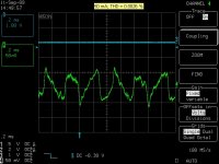
)I simply wired up a simple EF output stage (10 Ohm emitter resistor) using MJE15030/31. Output BJTs are biased at 2.8 mA with a 500 Ohm pot connected between BiasP&M. This bias level is not sufficient for class A operation for practical headphone loads. Higher bias level will be evaluated later.
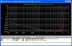
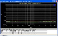
Here are some test data.
Rails: +/- 20 V from a test bench supply
Output noise level: 9.5 uV (22 Hz - 22 kHz)
Output DC level: 0.5 mV
Here are some test data.
Rails: +/- 20 V from a test bench supply
Output noise level: 9.5 uV (22 Hz - 22 kHz)
Output DC level: 0.5 mV
Attachments
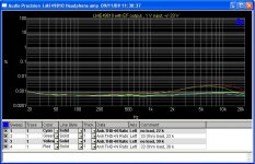
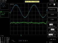
I changed the pot trim to 5 K by which bias level can be increased. At 100 mA idle current, the performance is super! Output noise slightly increases to 12 uV (22 Hz - 22 kHz). With 400 Hz high-pass filter inserted to filter hums, it reduces to 8.2 uV.
I run the tests for rails +/- 15 V. No noticeable problem observed.
I run the tests for rails +/- 15 V. No noticeable problem observed.
Attachments
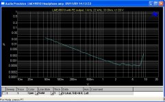
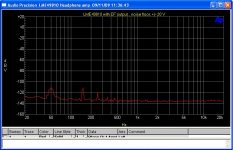
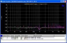
THD+N residual for various biasing points. THD+N is very low when bias current is 3 mA. It does not decrease but increase by increasing the bias. Is gm-doubling (D. Self) causing higher distortion in 10/50 mA?
Attachments

Last edited:
Personally I think I really good opamp plus a buffer is better and +-15 V supply voltage is more than enough. An idea would be to design a really small amp.I am planning to use some my LME498xx driver boards to build a headphone amp. Output devices will be MJE15030/31 since I have some of them.
Before I start doing the output stage. Let me try to use 49810 to direct drive my AKG K240. And see how does the chip perform at low rails < +/-20 V.
Last edited:
if these are the 600 Ohm monitors with 90 dB/V sensitivity then I certainly wouldn't settle for +/-15 drive - bridging gets closer but a discrete output with +/-45 Vsupply would be needed to drive them to 120 dB SPL without clipping
of course the transistor choice is still an order of magnitude too big with only 70mA required by the headphones
AKG K240 55 Ohm "Studio" version would seem to be quite simply served by something like the TPA6120
of course the transistor choice is still an order of magnitude too big with only 70mA required by the headphones
AKG K240 55 Ohm "Studio" version would seem to be quite simply served by something like the TPA6120

An idea would be to design a really small amp.
Do you mean a headamp or 498xx power amp? I am planning to do the later: a low power (<50W) 498xx + ThermalTrak amp on compact single board.
I meant a physically small amp.
HERE is one example, but what takes up room is really the power supply itself, specially if you got a few high capacitance caps in there and a half decent toroid adds to the weight too

LME vs. LM 6245
You could couple the LMEs parallel ( 22 Ohms in each output to compensate the differences in gain - I did this in a preamp to drive a 600 Ohms output transformer (Jensen)).
G
Peter
AFAIK is LME the high voltage version of LM (+-24V vs. +- 15V).Why not try using LM4562 and output buffer like BUF634 or better HA-5002?
You could couple the LMEs parallel ( 22 Ohms in each output to compensate the differences in gain - I did this in a preamp to drive a 600 Ohms output transformer (Jensen)).
G
Peter
Why not try using LM4562 and output buffer like BUF634 or better HA-5002?
BUF634 in 5 pin configuration is $12 on digikey where as MJE15030/31 $1.72
Imax is 250mA VS 4A for the MJE's
ANd whats makes it even better is i have 4 pairs on hand along with 3 LME49810's

Nice idea and good results. I was googling for this kind of headamp after some reading on the lme drivers IC.
Panson, Could you post the complete schematic with values? About 4x gain and 100mA+ for each output transistor is very close to my needs.
I'm trying many different headphone amps this year
Panson, Could you post the complete schematic with values? About 4x gain and 100mA+ for each output transistor is very close to my needs.
I'm trying many different headphone amps this year
Wow, old thread. You can find the schematic in the LME49600 datasheet. Just change the feedback resistors to get the desired gain. I'd be surprised if 12dB is actually needed, though, and probably neither is a high current buffer like the LME49600 (my earbuds run plenty loud on MAX4477s).
The TL032 and TL072 are good defaults for servos and the LME49880's worth a look if one wants BOM bragging rights.
LME49600's a bit cheaper. LMH6321 is almost identical to the 49600 and half the price. And somehow I'm not sure having headphone amplifier with a 4A output current is a feature.BUF634 in 5 pin configuration is $12 on digikey where as MJE15030/31 $1.72
What tomchr doesn't mention is his DC servo, as I recall, uses a JFET op amp instead of the LME49720 shown. I've commented on this in other threads but the LME49720's input bias and offset make it, like most any other BJT op amp, a horrid choice for a DC servo, especially on with a 1M tank impedance. I have no idea what National's apps engineers were thinking.I have gotten really good results with the LME49600 and a LME49710 used as a DC servo. The circuit is outlined in the applications section of the LME49600 data sheet.
The TL032 and TL072 are good defaults for servos and the LME49880's worth a look if one wants BOM bragging rights.
Last edited:
- Status
- This old topic is closed. If you want to reopen this topic, contact a moderator using the "Report Post" button.
- Home
- Amplifiers
- Chip Amps
- LME498xx Based Headamp