If the output stage of a CD player/pre-amp is a simple non-inverting op amp set up in the following ways:
1) Op amp output => 100 ohm series resistor => RCA jack
2) Op amp output => 10k ohm parallel resistor to the ground (not part of the loop) => RCA jack
If the op amp has zero output impedance (being perfect!):
What's the output impedance of the CD player/Pre-amp and what's the load resistance the op amp sees in set-up 1?
What's the output impedance of the CD player/Pre-amp in set-up 2?
pacificblue said:0 + 100 = 100
0 || 10k = 0
Thanks for answering the output impedance questions!
If the next stage has a 10k parallel resistor to the ground (an input resistor), would 10K be the load resistance the op amp sees in set-up 1 and 5k in set-up 2?
the opamp sees the two 10k in parallel, so yes you are right, 5k is the load.
If you fit DC blocking caps at the output and input of your equipment then add a grounding resistor at the RCA of both the output and input.
This grounding resistor gives a load if the RCA is left open circuit.
It also takes any leakage through the blocking cap to ground. This helps stop pops and bangs if you ever connect/disconnect hot!
The grounding resistor can be any value from 100k to 2M2. Not 10k.
I prefer the higher end. I also prefer Zin~50k.
AndrewT said:the opamp sees the two 10k in parallel, so yes you are right, 5k is the load.
If you fit DC blocking caps at the output and input of your equipment then add a grounding resistor at the RCA of both the output and input.
This grounding resistor gives a load if the RCA is left open circuit.
It also takes any leakage through the blocking cap to ground. This helps stop pops and bangs if you ever connect/disconnect hot!
The grounding resistor can be any value from 100k to 2M2. Not 10k.
I prefer the higher end. I also prefer Zin~50k.
Thanks for the clear explanation. Yes, a grounding resistor in high values following the op amp output would enable me to use smaller caps (more choices and lower cost), which is very helpful.
Now, I would like to place a 24-step 10K ladder-type attenuator after the op amp output stage. According to the this calculator:
http://homepages.tcp.co.uk/~nroberts/atten.html
in the first 8 steps, the ground resistors (Ry) in the attenuator will have values less than 100 ohm. Even with high values grounding resistors elsewhere, those low value resistors in the attenuator will lead to very low load resistance for the op amp due to parallel resistance. Am I correct? If I am, why do people say that ladder-type attenuator provides constant load to the source at the specified value (10K attenuator = 10k load)?
Thanks!
And for the stage after the attenuator:
Let's say that it is a non-inverting LM1875/3875 amp with a 22x gain set by 22k/1k resistor and an 22k input grounding resistor. What would be the input resistance the amp would see? The 22k set by the input resistor, or the value calculated by paralleling all the grounding resistors in between the input of the LM chip and the output of the op amp?
Thanks!
Let's say:
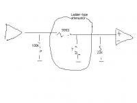
Op amp output=>100k ohm parallel/grounding resistor => 9993 ohm series resistor Rx => 7 ohm parallel/grounding resistor Ry => 22K ohm input parallel/grounding resistor for LM1875 => the + input of LM1875
The 9993 ohm series resistor Rx and the 7 ohm grounding resistor Ry are taken from Step No. 4 (Attenuation = 63 dB, a random choice) of a 24-step 10k ladder type attenuator, calculated from here:
http://homepages.tcp.co.uk/~nroberts/atten.html
If the calculator for the ladder-type attenuator is correct, isn't it true that the 7ohm Ry would make the load resistance for the op amp around 6.99ohm (100k, 7, and 22k parallel), which is very low? The values of Ry also varies greatly throughout the 24 steps. Why do people say that a ladder-type attenuator gives a constant load to the source? And what is the input resistance LM1875 sees in this set up, 22k ohm or 6.99 ohm? Thanks!
AndrewT said:I told you to draw yourself a diagram.
The 10k stepped attenuator has two legs the high resistance leg is in series with the signal line the low resistance leg goes to ground.
LOOK at it.
Yes, the low resistance one is the 7 ohm grounding resistor Ry I am talking about (each step in a ladder-type attenuator is constructed with one series resistor and one parallel resistor, am I right?) And this resistor is in parallel with the 100k at the op amp output and the 22k at LM1875's input. Is there something I am missing? I am really confused now.
Hi,
the 7r0 is parallel to the 22k.
The resistance of this // pair is 6r998
The series resistor adds 9993r to this, giving 9999r998.
The next parallel pair are 100k//9999r998 giving 9090r907
Notice that you have 7r and 22k and 100k and the 10k attenuator and the impedance seen by the source is within 10% of 10k.
You have omitted the series resistor in the source and omitted the series resistor in the power amp (receiver) input.
You have also omitted the input filters. These all have an effect, but again if they are chosen well will alter the 10k only slightly.
Now change that 100k in the source to 2M2 and see what you get with all the filters and resistors in place.
That is the case looking from the source into it's load.
You need to repeat the whole process looking from the receiver input back through the string of components to see the source resistance presented to the input.
You will find it is dominated by the 7r0.
We can talk about the effect that this variable (stepped) resistor has on the receiver once you understand the simple parts.
AndrewT said:the 7r0 is parallel to the 22k.
The resistance of this // pair is 6r998
The series resistor adds 9993r to this giving 9999r998.
The next parallel pair are 100k//9999r998 giving 9090r907
Notice that you have 7r and 22k and 100k and the 10k attenuator and the impedance seen by the source is within 10% of 10k.
You have omitted the series resistor in the source and omitted the series resistor in the power amp (receiver) input.
You have also omitted the input filters. these all have an effect but again if they are chosen well will ater the 10k only slightly.
Now change that 100k in the source to 2M2 and see what you get with all the filter and resistors in place.
That is the case looking from the source into it's load.
You need to repeat the whole process looking from the receiver input back through the string of components to see the source resistance presented to the input.
You will find it is dominated by the 7r0.
we can talk about the effect that this variable (stepped) resistor has on the receiver once you understand the simple parts.
I got it. And changing the 100k to 2m2 will make the impedance seen by the source much closer to 10k (2m2//9999r998). Thanks.
Yes, I omitted the filter cap and other series resistors for a simpler graph.
no.mudihan said:From the receiver's point, it would be
(100k+9993)//7//22k, am I right?
You must put in all the missing components.
Rs of the source is absolutely crucial to this source impedance, particularly at low attenuation settings.
Rs' =[(((Rs//100k) + 9993r)//7r//100k//22k) + Rfilter].
If both 100k become 2M2, you can virtually ignore them in these low impedance interconnections.
And when you look at the attenuator in detail you will find that the designer forgot, or chose to ignore, the effect that Load impedance has on the published settings.
22kZin and a 10kpot are particularly bad. 100kZin and 10kpot are much better. But better still, the designer should specify what load impedance is required to achieve his declared attenuator settings.

- Status
- This old topic is closed. If you want to reopen this topic, contact a moderator using the "Report Post" button.
- Home
- Amplifiers
- Chip Amps
- Op amps: output impedance and load resistance