Help Needed
Ok, I'll give this a try. Are you saying that I can run both board off these two transformers if wired up in this way??
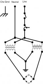
It need 4 leads coming out of it. Right now you have 0V and 24V rather than 24/0/24. So Troys suggestion will most likely be your solution. Use two of those transformers and twist together two of their leads so that you can make two measurements with the other leads. Take lead ABCandD. Twist BandC together. Measure from A to BC and measure from D to BC. You will want to see voltages of +24 and -24. Then take BC and take that to the ground on your boards. The wire BC should be equal to 0V. Uriah
Ok, I'll give this a try. Are you saying that I can run both board off these two transformers if wired up in this way??
Help Needed
And anyway, I suppose the bulb would have lit up if this was the case.
What I suspect the most is that there has been a short between the heatsink and the printed circuit on the underside of the board, altough it must be really bad luck for this to happen on the two boards at once.
And anyway, I suppose the bulb would have lit up if this was the case.
Help Needed
Hi All,
The good news is that with the two transformers on the one board as advised, it worked fine and gave a fantastic sound even on some very old speakers I used for the test. Many many thanks to you all.
The bad news is that when I wired up the second board - on its own -in the same way, it was silent.
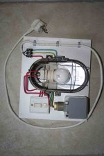
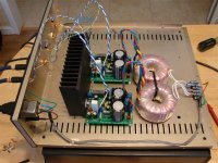
I got out the multi-meter and started comparing resistances between the two boards. There was imediately a very significant difference. The resistance between the two centre terminals of the 10000µF caps (see attached) was zero on the board that worked and very high on the board that didn't work.
Anybody any suggestions.
Hi All,
The good news is that with the two transformers on the one board as advised, it worked fine and gave a fantastic sound even on some very old speakers I used for the test. Many many thanks to you all.
The bad news is that when I wired up the second board - on its own -in the same way, it was silent.
I got out the multi-meter and started comparing resistances between the two boards. There was imediately a very significant difference. The resistance between the two centre terminals of the 10000µF caps (see attached) was zero on the board that worked and very high on the board that didn't work.
Anybody any suggestions.
Attachments
Re: Help Needed
If both boards are in the same chassis then put the output of the trafo on a terminal strip and just run parallel leads to however many Rev_C boards you have.
Tony X said:Would this work?
If both boards are in the same chassis then put the output of the trafo on a terminal strip and just run parallel leads to however many Rev_C boards you have.
Re: Help Needed
Picture of the other side please.
And you should have Zero resistance between those two points. Also you should have zero resistance from either of those points to the ground terminal faston.
Tony X said:Hi All,
The good news is that with the two transformers on the one board as advised, it worked fine and gave a fantastic sound even on some very old speakers I used for the test. Many many thanks to you all.
The bad news is that when I wired up the second board - on its own -in the same way, it was silent.
I got out the multi-meter and started comparing resistances between the two boards. There was imediately a very significant difference. The resistance between the two centre terminals of the 10000�F caps (see attached) was zero on the board that worked and very high on the board that didn't work.
Anybody any suggestions.
Picture of the other side please.
And you should have Zero resistance between those two points. Also you should have zero resistance from either of those points to the ground terminal faston.
Help Needed
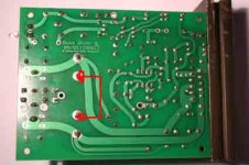
Indeed, on the good board, all are at zero. On the faulty board, the only zero is between the upper cap point (right hand looking away from heatsink) and the faston. I have to admit that during the initial build, I desoldered and replaced one of the 10000µF caps because it was not sitting down right. I don't know which one it was, but I may have overheated it in the process. I don't have a capacitance scale on my multi.
Thanks again to everyone for their helpful comments. We will win I am sure.
See post N° 54 to this thread. If not clear enough, I'll take another.Picture of the other side please.
And you should have Zero resistance between those two points. Also you should have zero resistance from either of those points to the ground terminal faston.
Indeed, on the good board, all are at zero. On the faulty board, the only zero is between the upper cap point (right hand looking away from heatsink) and the faston. I have to admit that during the initial build, I desoldered and replaced one of the 10000µF caps because it was not sitting down right. I don't know which one it was, but I may have overheated it in the process. I don't have a capacitance scale on my multi.
Thanks again to everyone for their helpful comments. We will win I am sure.
Check for voltage across the suspected cap. If none, short it to drain any residual. Then mesure resistance across the suspected cap. Should change as the cap charges from the MM battery.
Pwr it up and see if the DC voltages are present on the primary filter caps. If not solder a smaller temp cap on the bottom to see if you then have DC voltages.
Pwr it up and see if the DC voltages are present on the primary filter caps. If not solder a smaller temp cap on the bottom to see if you then have DC voltages.
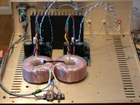
I'm using a pair of ILP toroids that I got off ebay a few months ago that look remarkably identical to the ones in the toroid GB here.
My heatsinks arrived yesterday and I got my casework all finished up last night and got as far as mounting the toroids and wiring up the primaries of the xformers.
I was reading through the threads again, I was looking at Peter and Uriah's pics and now I am confused on the secondary winding connections. I was thinking all I had to do was parallel the secondaries to AC1 and AC2 and connect PGND to chassis ground but apparently that is wrong.
I've never wired up a dual secondary xformer in the way I saw in the pics, is it kind of like a center tap?
If I'm figuring it out right, I'll need to tie together the center leads and connect them both to PGND on the PCB and use the 2 outer leads for AC1 and AC2 right?
The part I don't understand at all is do I need to connect an additional ground wire from the pcb to chassis ground? Or do I not need to connect PGND on the pcb and connect the center leads to chassis ground instead? I'm a little confused by the sketches a few posts up. I would think the pcb needs to be grounded but I'm confused and want to be set straight. Advice is appreciated, thanks!
Help Needed
Yes, resistance builds across both caps with time.
To clarify, which Caps (Cn?) do you refer to as primary input filter?
Check for voltage across the suspected cap. If none, short it to drain any residual. Then mesure resistance across the suspected cap. Should change as the cap charges from the MM battery.
Yes, resistance builds across both caps with time.
see if the DC voltages are present on the primary filter caps
To clarify, which Caps (Cn?) do you refer to as primary input filter?
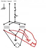
The Mauro Rev_C does NOT need to be tied to earth or chassis ground!!!
If you wanted to for some reason you could do as Mr. Pass does and tie a CL60 between Pwr grnd and chassis ground. Or a 10Ohm 5 Watt resistor bypassed with a cap or a....
Several ways to tie the two points together, but none are needed.
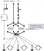
Dual secondaries:
one lead from each secondary tie at a junction point.
land the other lead from each secondary on seperate points.
Run 3 wires from the junction points to as many Rev_C boards as you have providing your trafo's are sized accordingly.
Look at my pic. I tied the yellow and black lead together and ran one "green" wire to the PCB.
If I were to use one trafo for multiple PCB's I would have used a terminal strip as a junction point..
If you wanted to for some reason you could do as Mr. Pass does and tie a CL60 between Pwr grnd and chassis ground. Or a 10Ohm 5 Watt resistor bypassed with a cap or a....
Several ways to tie the two points together, but none are needed.
Dual secondaries:
one lead from each secondary tie at a junction point.
land the other lead from each secondary on seperate points.
Run 3 wires from the junction points to as many Rev_C boards as you have providing your trafo's are sized accordingly.
Look at my pic. I tied the yellow and black lead together and ran one "green" wire to the PCB.
If I were to use one trafo for multiple PCB's I would have used a terminal strip as a junction point..
Attachments
troystg said:The Mauro Rev_C does NOT need to be tied to earth or chassis ground!!!
If you wanted to for some reason you could do as Mr. Pass does and tie a CL60 between Pwr grnd and chassis ground. Or a 10Ohm 5 Watt resistor bypassed with a cap or a....
Several ways to tie the two points together, but none are needed.
Dual secondaries:
one lead from each secondary tie at a junction point.
land the other lead from each secondary on seperate points.
Run 3 wires from the junction points to as many Rev_C boards as you have providing your trafo's are sized accordingly.
Ok, thank you for clearing that up for me! I'm pretty sure I get it now, hopefully I'll have a working amp at some point tonight
Coreyk78 said:
Ok, thank you for clearing that up for me! I'm pretty sure I get it now, hopefully I'll have a working amp at some point tonight
Note in my pictures that the input RCA's are insulated as are the output binding posts (yes one is reversed!).
At no point is the PCB tied to the chassis. I think even the standoffs are isolated on the PCB...
Attachments
- Home
- Amplifiers
- Chip Amps
- The new "My Ref" Rev C thread