jaudio said:Hi
Can anyone point me to the post that uses a trimmer and the supply voltage (Vcc and Vee) the null dc offset
Apply a small voltage into one of the inputs, this can be derived from the power supply. If your output offset is 10 mV, you would introduce -10 mV into the feed-back circuit.
jaudio said:Hi
Can anyone point me to the post that uses a trimmer and the supply voltage (Vcc and Vee) the null dc offset
Attachments
Yes you can, it will work with any differential amplifier. Why do you use a coupling capacitor do you not have a split supply?ide2003 said:Hi Nico Ras,
Saw your schematic, thanks, I'm a noob, can I use this for LM3886 chip?. I did not like the sound with coupling capacitor, but do not want my speaker to suffer..
regards
TPS
Nico
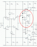
Like Nico Ras posted, this is the same way used in Krell KSA-100
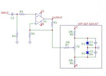
to provide some current to adjust the DC-offset.
If looking at attachment here you see two diodes around the 0V.
These gives a span of +- 0.7 Volt reference.
So can add both negative or postive adjust current.
The resistor values used are important.
Because these resistors:
R15, R16, R17(pot), R18 will give a resistance that is parallell to R9 - 475 Ohm.
475 Ohm resistor is a part of the feedback divider, which controls the gain of amp.
If offset resistance was 475R, than this would give the amplifier would have twice the gain!
( 475 parallelled with 475 is = 237.5 )
But as R15,R16,R17,R18 gives a total resistance of >25000 Ohm
which is >50 times larger than 475R
the offset adjust will only effect, increase the gain with (~1/50) ~2%.
If you can not get good adjustment with large enough resistors
then you have to increase the reference voltage.
For example use 2+2 diodes, giving +-1.4 Volt, instead of +-0.7 Volt.
Attachments
Nico Ras said:
Yes you can, it will work with any differential amplifier. Why do you use a coupling capacitor do you not have a split supply?
Nico
Thanks Nico, I have first tried without coupling capacitor, sounds very transparent..then for safety sake's added a MKT 2.2uF cap, the magic is gone..I don't have a budget for expensive cap and I use split supply. Will try your scheme soon

TPS
ide2003 said:Hi Nico Ras,
Saw your schematic, thanks, I'm a noob, can I use this for LM3886 chip?. I did not like the sound with coupling capacitor, but do not want my speaker to suffer..
regards
TPS
This reply is regarding the input circuit, not the NFB. . .
DC offset with LM3886? Most of the documents indicate a 20k pot + a 20k resistor. That's a 10k input impedance and it lowers DC offset nicely. Sometimes, its like this: buffer, cap, 20k linear pot (load), 20k resistor (load), lm3886
So, you see, if you use an input filter cap, that you still to make sure your input impedance resistor is 10k.
Next. . .
Here's what doesn't work:
pot, then cap, then 20k load = big dc offset!
cap then 20k load = big dc offset!
So change that to 10k resistor.
Edit: Take a look at the very first page of LM3886.PDF from National Semiconductor.
danielwritesbac said:
This reply is regarding the input circuit, not the NFB. . .
DC offset with LM3886? Most of the documents indicate a 20k pot + a 20k resistor. That's a 10k input impedance and it lowers DC offset nicely. Sometimes, its like this: buffer, cap, 20k linear pot (load), 20k resistor (load), lm3886
So, you see, if you use an input filter cap, that you still to make sure your input impedance resistor is 10k.
Next. . .
Here's what doesn't work:
pot, then cap, then 20k load = big dc offset!
cap then 20k load = big dc offset!
So change that to 10k resistor.
Edit: Take a look at the very first page of LM3886.PDF from National Semiconductor.
hi there danielwritesbac, appreciated your tips.
will check mine, schem. attached, I use 50k pot, C1=2.2u, R1=1k, R2=20k in that order.. is this the culprit of 'big' dc-offset?
thanks
TPS
Attachments
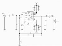
ide2003 said:hi there danielwritesbac, appreciated your tips.
will check mine, schem. attached, I use 50k pot, C1=2.2u, R1=1k, R2=20k in that order.. is this the culprit of 'big' dc-offset?
thanks
TPS
Yes it is.
You can change R2 to 10k and then you can measure lower dc offset as the result. This may change the capacitor size needed at C1.
Tip:
Imagine. . . the pot needs protected from DC entrance, which can come from a buffer, preamp, or source.
Imagine. . . a future buffer/pre project. Have a look at some examples and see how they will connect to your amplifier.
EDIT: I will conduct an experiment today with both feedback and input load as 10k. Also, I'll set "nfb seeks ground" the same value as "input series" resistor. This is the way of a balanced amplifier; however, there's an additional step that I either don't know or can't remember.
danielwritesbac said:EDIT: I will conduct an experiment today with both feedback and input load as 10k. Also, I'll set "nfb seeks ground" the same value as "input series" resistor. This is the way of a balanced amplifier; however, there's an additional step that I either don't know or can't remember.
WOW!!!
The analog meter didn't budge on its most sensitive setting. Normally, it'll show about 45mv on my amps.
The digital meter on its "200m" scale read 00.1. My fingers could get it to read 08.2, so, apparently my body makes more dc offset than this amplifier. It could be paralleled without the typical heat penalty.
I had to use a smaller-than-usual gain setting because there was too much.
The bass is nice!
danielwritesbac said:
WOW!!!
The analog meter didn't budge on its most sensitive setting. Normally, it'll show about 45mv on my amps.
The digital meter on its "200m" scale read 00.1. My fingers could get it to read 08.2, so, apparently my body makes more dc offset than this amplifier. It could be paralleled without the typical heat penalty.
I had to use a smaller-than-usual gain setting because there was too much.
The bass is nice!
men!. you're fast!..thanks, so many to try..so little time..
TPS
don't quite understand this, danielwritesbac, a schematic is great thanks b4
EDIT: I will conduct an experiment today with both feedback and input load as 10k. Also, I'll set "nfb seeks ground" the same value as "input series" resistor. This is the way of a balanced amplifier; however, there's an additional step that I either don't know or can't remember.
AndrewT said:and you know what means.
nice that you come-by AndrewT, you know, this EE talks that keeping me going gaa-gaa all the time..I can read the schem, can solder, do a nice mech job..but gave up on these..

TPS
AndrewT said:we've all given up trying to persuade Daniel to use the conventional language that we can all understand.
I forgot how to call "sides" of a voltage divider. Low leg? High leg?
Sorry about that.
Since this isn't using a DC null circuit, and so its off topic, I moved the discussion of my experiment (soon to list a schematic) over to: http://www.diyaudio.com/forums/showthread.php?s=&threadid=134196
- Status
- This old topic is closed. If you want to reopen this topic, contact a moderator using the "Report Post" button.
- Home
- Amplifiers
- Chip Amps
- looking for null circuit