Hey everyone, i'm new to the forum and came across this project a couple of weeks ago and now i'm hooked and want to build a 2 ch stereo amp.
The thing that i'm still confused about is the transformer, it seem like there is a lot of options I usually buy from digikey.com and when looking through there site it asks for Parallel Output Voltage @ Current and Maximum Power now I know for 2 amps, I need a dual secondary so if anyone can point me to the right one to buy from there because this seem to be the most expensive part of the whole project prices ranging from 60 to 120.
Or if there is a better place to get them from in Canada that would be great too!
Thanks
download the datasheet and any other information the manufacturer publishes for your potential chip.keaster said:i'm new to the forum and came across this project a couple of weeks ago and now i'm hooked and want to build a 2 ch stereo amp.
Decide what speaker impedance you want to use, now and in the future.
Consult the datasheet and find the maximum DC voltage the chip can accept for your chosen worst case speaker impedance.
Now select a transformer AC voltage to give that maximum DC supply.
If you use a 3886, then for 4ohm speakers you can use 15Vac or 16Vac or 18Vac and if you're careful to keep the chips cool you can get away with 20Vac.
Select a centre tapped or dual secondary for a monoblock amplifier and use a single rectifier arrangement.
For a stereo amplifier, select a dual secondary transformer and use a dual rectifier arrangement.
Sorry forgot the link
http://www.plitron.com/shopping/shopexd.asp?id=171
http://www.plitron.com/shopping/shopexd.asp?id=171
That link is a 38Vac which is way to high.
This is the 20Vac version..
http://www.plitron.com/shopping/shopexd.asp?id=163
This is the 20Vac version..
http://www.plitron.com/shopping/shopexd.asp?id=163
read the datasheet again.
What speaker impedance have you decided to design for?
Find the sections that deal with supply voltage and speaker or load impedance. Follow the manufacturer's advice. If there is a part you don't understand ask a specific question. We're here to help.
Find the sections that deal with heatsinks and power dissipation.
Here, I suggest you at least double the dissipation capability that National recommends as a minimum.
Again come back with any or all questions.
Hello
I finally got around to finishing one of these power supplies.
I am feeding 25v secondaries into this power supply via a bridge rectifier. I have connected a 230R resistor between either Vout + or Vout - and I'm getting a reading of 36vdc.
I am using a 27v zener to set the voltage, would I be right in thinking the voltage is too high?
Thanks
Richard

Hi trip,
The two followers each drop ~0.6V. the output should be ~27-1.2 ~25.8Vdc.
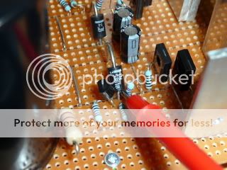
Start by measuring the voltage from ground to all the components and list them here. Do one channel only. Check to see if any component gets hotter than the rest. The pass transistor should be cold if it is not dropping any voltage.
Is the 230r load resistor getting VERY hot? 36V across 230r is 5.6W and that resistor looks like it might be a 1 or 2W carbon composition. Is it still drawing any current?
The two followers each drop ~0.6V. the output should be ~27-1.2 ~25.8Vdc.
Start by measuring the voltage from ground to all the components and list them here. Do one channel only. Check to see if any component gets hotter than the rest. The pass transistor should be cold if it is not dropping any voltage.
Is the 230r load resistor getting VERY hot? 36V across 230r is 5.6W and that resistor looks like it might be a 1 or 2W carbon composition. Is it still drawing any current?
AndrewT said:Hi trip,
The two followers each drop ~0.6V. the output should be ~27-1.2 ~25.8Vdc.
Start by measuring the voltage from ground to all the components and list them here. Do one channel only. Check to see if any component gets hotter than the rest. The pass transistor should be cold if it is not dropping any voltage.
Is the 230r load resistor getting VERY hot? 36V across 230r is 5.6W and that resistor looks like it might be a 1 or 2W carbon composition. Is it still drawing any current?
Hi Andrew
I will have a look tonight and will post the results.
The resistor on the output got very hot last night, I turned the power supply on this morning and noticed the 3A fuse in the ‘light bulb tester’ plug top had blown.
I’ve lost count the number of times I have checked this board prior to powering up!
Richard
Hi,
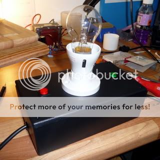
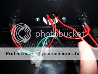
is your light bulb tester properly wired up?
It should be unlit when no load is present.
If the bulb lights when you insert a big load into the output socket then it's probably right, but it should never blow a 3A fuse, that's indicating the bulb passed more than 700W!!!
is your light bulb tester properly wired up?
It should be unlit when no load is present.
If the bulb lights when you insert a big load into the output socket then it's probably right, but it should never blow a 3A fuse, that's indicating the bulb passed more than 700W!!!
AndrewT said:Hi,
is your light bulb tester properly wired up?
It should be unlit when no load is present.
If the bulb lights when you insert a big load into the output socket then it's probably right, but it should never blow a 3A fuse, that's indicating the bulb passed more than 700W!!!
As sure I was about the power supply
")
I have bought the components to make the Nick’s latest light bulb tester (including on-off testing switches) I think this should be the next project!
Tripmaster said:
As sure I was about the power supply
I have bought the components to make the Nick’s latest light bulb tester (including on-off testing switches) I think this should be the next project!
Hi
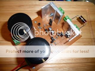
I have attempted to assemble another light bulb tester this evening.
Would you mind checking my wiring, I think its ok?
Thanks
Richard
OK, right then...I have connected the light bulb tester to my power supply and I get 34.2vdc from the output. I then measured the voltage at the 27v zener (pictured below) this read 26.63vdc.
When ever I press the 'on button' on the light bulb tester the bulb glows for a second
When ever I press the 'on button' on the light bulb tester the bulb glows for a second
- Home
- Amplifiers
- Chip Amps
- Chip amp power supply- a beginners guide