tent said:Hi again,
ok current status is: I checked with 3.15A fuses and they did also blow and now with 4A fuses I have a stable setup even by turning on and off several times, so this seems the best for my two 200VA 2x13.5V toroids, and now I can read after the bridge a 18.7V between V+/- and GND.
Next step will be connecting amp and then speakers.. after I connect amp and check how many milliamps there are on the output for the speakers, can I do it simple as is with my multi or is it better to put some load between them like a 10ohm 5W resistor?
I don't think you really need to measure the mA output to the speakers, but if you want to a resistor would be better and you'll have to have a RMS capable meter.
So now the missing questions for me are:
- Is it possible to use two bridges with my setup? (is it non sense? just parallel the out on two bridges, etc.)
- Is it possible to use just one of my two 13.5V toroids (with single secondaries) and the one bridge? (connectng only AC1 and AC2_, nothing on the 0V?)
- Would it be wiser/sinically better to change the 1500uF caps with some 10000uF or any other value? I also put under the current 1500 caps a 2200 resistor at 2W.
- Is it wise/sonically better to snubber the bridge? If so would you suggest me on this PSU+trafos something like a 2.2nF between the secondaries coming out the toroid?
Thanks in advance,
tent:wq
- Yes it's possible, but it seems a growing amount of expense and time for a 20W mono amp. Since the pair of 200VA transformers and 10,000uF capacitance is quite a lot for a 20W mono amp, you will probably have good regulation and have minimal benefit from a second bridge rectifier. This is audio though, the only way you can really know is to audition it both ways.
- It's possible to use only one of your transformers but would require building the amp itself a different way with coupling capacitors on the output to the speakers because then the amp output would swing between V+ and Gnd instead of V+ and V-. I would not recommend doing it this way, coupling caps large enough to handle the output power tend to become lossy at higher frequencies.
- 10,000 uF is overkill for a mono 20W amp, I would go with about 2,000 to 4,000uF at most, but some people have in the past felt that their 60W+ gainclones actually sound better if those use small 1,000uF capacitors so to duplicate their result you would use even less with a single channel at 1/6th the total output power.
Essentially everyone likes something different but my recommendation is roughly 220uF low-esr caps as close to the chip pins as possible, then about 2200uF on the PSU board. In other words the more capacitance you have on the amp board the less is needed on PSU board. Even then you are building a power supply that is overkill for this amp, personally I would save the PSU board for the next amp and just put a plain silicon diode and pair of 2200uF caps on a stripboard for this amp as you don't even need the thicker traces or wire holes for the size wire carrying this lower level of current.
- Some say they can hear a difference with a bridge snubber, some say they can't. Some say put just a single cap right after the bridge, others across each diode, others put a series resistor with any cap. If you have the caps lying around you might as well use them, and the suggested value seems to be in the ballpark, but there is another topic that shows how to calculate them but I can't remember the name of it, maybe someone else will remember or a forum search will find it.
Hi !
well thanks a lot for your answers, and yes: you convinced me to finish asap with this amp (I'm almost finished and will post the photos) and go on further with a LM3886 one asap!")
tent:wq
PS: going to stick to 1500uF and some snubbers here and there and seeing what changes.
BTW: any idea where is the PLUS of the C2 eletrolythic cap??
http://www.chipamp.com/images/lm1875-3.jpg
well thanks a lot for your answers, and yes: you convinced me to finish asap with this amp (I'm almost finished and will post the photos) and go on further with a LM3886 one asap!
tent:wq
PS: going to stick to 1500uF and some snubbers here and there and seeing what changes.
BTW: any idea where is the PLUS of the C2 eletrolythic cap??
http://www.chipamp.com/images/lm1875-3.jpg
tent said:Hi !
well thanks a lot for your answers, and yes: you convinced me to finish asap with this amp (I'm almost finished and will post the photos) and go on further with a LM3886 one asap!
tent:wq
PS: going to stick to 1500uF and some snubbers here and there and seeing what changes.
BTW: any idea where is the PLUS of the C2 eletrolythic cap??
http://www.chipamp.com/images/lm1875-3.jpg
You won't find + or -, this cap is "Non Polarized" or "Bipolar" one.
I've used a 22µF/50v Nichicon MUSE ES as C2.
Can be found here :
http://www.minisemi.com/Nichicon Muse capacitors.html
korben69 said:
You won't find + or -, this cap is "Non Polarized" or "Bipolar" one.
I've used a 22µF/50v Nichicon MUSE ES as C2.
Can be found here :
http://www.minisemi.com/Nichicon Muse capacitors.html
Uff you're right!
completely overseen it.. tent:wq
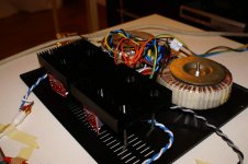
final prototype...
Hi all,
so I finally managed to finish the thing and plug it to my cd player!
I attach here some fotos of the current result before finishing the casing.
The only thing I have to say is that really the humm that is annoying me now is this trafo humming!! The loudpeakers and the rest seem really quiet.. but could it really be I have two really noisy toroids? are there differences between them? And of course, I now agree with ! that the power of this amp really limited is.. but anyhow I'll quickly move to a LM3886 now..
tent:wq
Attachments
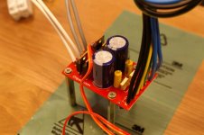
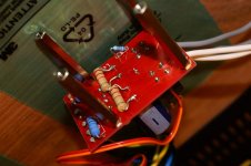
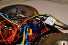
the two heatsinks are at V+ since no mica or such insulation was used to better dissipate and get better sound (somebody states this at least.. and so I simply decoupled it on the bottom plate by using plasic washes and screws (PVC) so nobody gets hurt..
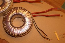
The two trafos on the background are really huge and heavy..
tent:wq
and so I simply decoupled it on the bottom plate by using plasic washes and screws (PVC) so nobody gets hurt.. The two trafos on the background are really huge and heavy..
tent:wq
Attachments
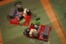
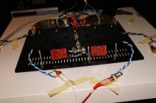
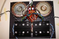
The last image of the work done.. you can see my idea on how to put things on my enclosure (I'll using one of those from hifi2000.it really gorgeous looking.. great manufacturer!)..
Any suggestions and hints are welcome and thanks for all the tips so far!!
tent:wq
Any suggestions and hints are welcome and thanks for all the tips so far!!
tent:wq
Attachments
you can certainly make things sound far more complicated than they are.
assemble a light bulb tester as instructed. Do the simple one without any switches. It will cost a very few dollars and is indepensible for all your future prototyping and modification work.
Connect one transformer to the mains, through the bulb tester.
switch on and measure the input voltage and the output voltage.
Switch off and lable the wire ends.
Disconnect this first transformer.
Connect the other transformer as before and measure and then lable.
Now connect the two transformers exactly dupicating the labeled wire ends. measure the two secondaries. They should be the same as before.
Connect one pair of secondaries to AC1 & AC1_, connect the other secondary to AC2 & AC2_ . Check the pSU voltages.
Remove the bulb tester and check the full voltages from the PSU.
Job done.
Reinsert the bulb tester and assemble the first amplifier. Test/measure again.
Add on the various stages check and testing at every stage.
Thank you Andrew,
yes I will certainly build also the light bulb tester before starting with the next project, didn't do it before since the diagram on how to do it semed complicated and not so clear at first glance: is thre a simple version around of the ones without switches as you where mentioning?
But now my real priority is to understand if all the toroids are so noisy or if only this specific ones I have (augmented by the fact they are TWO) that are so nasty.. ;(
Since I do not want to begin a new project if all the attention I try to put on having a clear output free of hum and hiss is then ruined by their noise itslef..
As mentioned, till now I had only experience with T-amps and they really promise what they are: not so powerfull but really crisp clear and free of humm (and till now I only own ones made with switching PSUs, not even something particularly designed on the PSU side!).
So in your experience of the gainclones you built as of today, especially the ones having toroids providing more than 200VA: can you hear them being turned on if nothing is playing on the CDs? Does it disturb you?
Kind Regards,
tent:wq
I'm interested in building a "regulated PSU" for my LM3886 gainclone project. I plan on building it for maximum output @ 4 ohms, just in case so I have a flexible system that'll work with a variety of speakers. So with a planned 25-30 Vcc, the continuous output would be ~68W (2x, stereo). After much reading I'd like to build Pedja's Discrete PSU (Module R), however on his site the listed schematic follows:
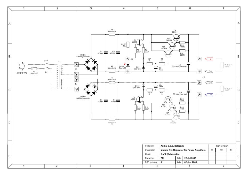
and on Nuuk's is:
Differences (Pro's & Con's)? R1-R4 are different, in the top schematic he mentions they are charging resistors for the second set of capacitors. Also neither include bleed resistors on the capacitors.
Looking at commonly available zeners' (25, 27, 28, & 30 V), in the module R manual he lists Vishay BZX79 which seem no longer to be manuf. What should I looked for, 500mW power dissipation, DO-35 package, etc...
Also trafo secondary voltage, the manual mention selecting a voltage at least 4V higher than the zener's with 3-4 V on top of that fine for headroom. Is this voltage pre or post rectification? i.e. if I chose to use a 27V zener, then would a secondary voltage of 22 V work (post rectification 31 V)? Finally VA rating conservatively 250VA should be enough, or more or less?
and on Nuuk's is:
An externally hosted image should be here but it was not working when we last tested it.
Differences (Pro's & Con's)? R1-R4 are different, in the top schematic he mentions they are charging resistors for the second set of capacitors. Also neither include bleed resistors on the capacitors.
Looking at commonly available zeners' (25, 27, 28, & 30 V), in the module R manual he lists Vishay BZX79 which seem no longer to be manuf. What should I looked for, 500mW power dissipation, DO-35 package, etc...
Also trafo secondary voltage, the manual mention selecting a voltage at least 4V higher than the zener's with 3-4 V on top of that fine for headroom. Is this voltage pre or post rectification? i.e. if I chose to use a 27V zener, then would a secondary voltage of 22 V work (post rectification 31 V)? Finally VA rating conservatively 250VA should be enough, or more or less?
tent said:Thank you Andrew,
yes I will certainly build also the light bulb tester before starting with the next project, didn't do it before since the diagram on how to do it semed complicated and not so clear at first glance: is thre a simple version around of the ones without switches as you where mentioning?
All you need to do is get a standard light bulb socket, the type that screws to a wall or ceiling. You then wire it in series with one of the AC inputs to the transformers.
But now my real priority is to understand if all the toroids are so noisy or if only this specific ones I have (augmented by the fact they are TWO) that are so nasty.. ;(
Since I do not want to begin a new project if all the attention I try to put on having a clear output free of hum and hiss is then ruined by their noise itslef..
Previously I thought you meant the toroids themselves were humming because the windings were loose. Do you mean there is no noise coming directly from them, only noise on the output of your amp?
If the noise comes directly from them, the fix is kind of hackish, you would take the outer wrap off and re-wrap it, ideally smothering the windings in non-conductive epoxy to fix the coils in place first.
If the hum or hiss is on the output of the amp, you don't have a shielded circuit so try totally enclosing it in a grounded metal housing. Also ground loops can make it hum, I can't tell so much from the pictures but see if you have any ground loops and are using a star ground topology.
As mentioned, till now I had only experience with T-amps and they really promise what they are: not so powerfull but really crisp clear and free of humm (and till now I only own ones made with switching PSUs, not even something particularly designed on the PSU side!).
I also tweaked a T-Amp and agree, really nice crisp sound but output power is very limiting if the speakers are not very high efficiency or more volume is desired. From what I recall a switching PSU causes a little distortion but some say it's livelier, that they consider it better that way. On mine I used a basic LM317 linear regulator and decided that was right for me.
So in your experience of the gainclones you built as of today, especially the ones having toroids providing more than 200VA: can you hear them being turned on if nothing is playing on the CDs? Does it disturb you?
Kind Regards,
tent:wq
Is the noise only when it's turned on or off? I don't remember on your chipamp chip, but some have a mute circuit built in which can address on/off pop. Beyond that, it shouldn't be that the toroids are oversized for the application.
You did not mention your source, is it AC grounded? We don't know the exact amp circuit either unless I overlooked you posting it. Does it make noise equally when the source is plugged into it (but not playing audio) and when it is not?
I have never built a Gainclone.tent said:So in your experience of the gainclones you built as of today, especially the ones having toroids providing more than 200VA: can you hear them being turned on if nothing is playing on the CDs? Does it disturb you?
The circuit sucks.
I have only worked with the 3886 chip and it switches on and off silently and plays adequately.
It is easily beaten by any competent discrete amplifier.
NO!!!!tent said:Next step will be connecting amp and then speakers.. after I connect amp and check how many milliamps there are on the output for the speakers, can I do it simple as is with my multi or is it better to put some load between them like a 10ohm 5W resistor?
check the output offset (mVdc) and the output noise (mVac) with various combination of input conditions and at start up and switch off. Do this with no load on the output.
Repeat with a dummy load (~8r0) and ensure you are not sending large offsets nor large voltage pulses to the speaker terminals before you add on the speaker load.
Use the bulb tester for every new combination or modification.
If the bulb stays off, this is where the switched version becomes handy. Just hold the bypass switch down to check the modification at full mains voltage.
Hmm. Once upon a time ago, gainclone meant only a clone of the commercial design, but I think we DIY'ers have moved far beyond that point by now.
Maybe we need to just abandon the term gainclone, BUT at the same time, a common term helps draw others into the hobby which can't be a bad thing.
Maybe we need to just abandon the term gainclone, BUT at the same time, a common term helps draw others into the hobby which can't be a bad thing.
- Home
- Amplifiers
- Chip Amps
- Chip amp power supply- a beginners guide