AndrewT said:Check the voltage across R2.
Check the voltage across the Zener. Check the voltage Vds across the FET.
These should add up to the supply voltage. I suspect that either the Zener is back to front and/or the FET is damaged.
Tripmaster said:R2 has the same voltage as output and the J309 has a reading of less than a volt.
now total the voltage drops across all three devices.Tripmaster said:Im not getting an output from the Zener
AndrewT said:
now total the voltage drops across all three devices.
Hi Andrew
I will do this tonight.
The voltage decreases the longer I leave the power supply powered. Is this going to lead to an inaccurate figure or should I wait a while between each component?
Does Vds stand for ‘voltage drain to source’?
Thanks
Richard
AndrewT said:yes,
Vds = Voltage Drain to Source.
Is the Zener the right way round?
This is the negative rail!!
It did cross my mind but the Zener symbol in the schematic faces in the same direction as the v+ side. Is this an error on the schematic?
It’s the first time I have built a circuit by following a schematic…and boy does it show!
")
AndrewT said:Hi,
the Black Band is towards the more positive voltage.
If you have +ve supply at the top, Zero volts from the supply in the middle and -ve supply at the bottom, then both Zeners "point" in the same direction - towards the more positive rail.
Thats ok then.
21.6V across the resistor explains why it's burning.
0.7V across the Zener indicates it's back to front, i.e. forward biased, check it's direction again.
J309 may now be damaged but fix the Zener & resistor first.
Buy yourself a plug board. A couple of £ from Maplin and many others. Ideal while your learning and continues to be useful long afterwards.
Save that expensive Veroboard for proved circuits.
AndrewT said:21.6V across the resistor explains why it's burning.
0.7V across the Zener indicates it's back to front, i.e. forward biased, check it's direction again.
J309 may now be damaged but fix the Zener & resistor first.
Buy yourself a plug board. A couple of £ from Maplin and many others. Ideal while your learning and continues to be useful long afterwards.
Save that expensive Veroboard for proved circuits.
Morning Andrew
Thanks for checking those figures
I'm not trying to challenge your advice, but when I measured the voltage across the Zener, before I cut the tracks and added a couple of links as per Audio1st diagram, I took a reading of 36v from this side of the Zener. Should the anode or cathode be connected to the drain pin of the J309?

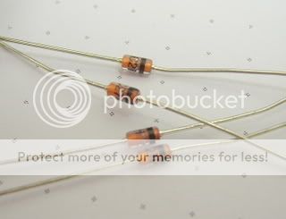
Zener Data Sheet
http://www.datasheetcatalog.org/datasheets/105/105630_DS.pdf
I have some spare parts to swap out the faulty components and will have a go at this tonight
Hi,
what power of Zener is that?
A 400mW glass packaged Zener will do the job better and cheaper. Rapid sell them for 2p each.
A 24V 400mW Zener requires at least 0.8mA (5%) to operate properly and better to have at least 1.7mA (10%) to operate well.
A 1.3W device asks for too much current to get around the knee in the I vs V curve.
I go over this sort of circuit with the meter, checking that each connection, of each component is connected to what it should be, and perhaps more importantly, that it is not connected to anything that it shouldn't be.
That can be a long and laborious job, but usually results in the circuit working first time.
Like Barry, my suspicion was that there was a short somewhere. Barry pointed pointed out one possibility, but there may be another one or two!
That can be a long and laborious job, but usually results in the circuit working first time.
Like Barry, my suspicion was that there was a short somewhere. Barry pointed pointed out one possibility, but there may be another one or two!
AndrewT said:500mW 27V need about 1.9mA to exceed 10% of rating. go for it.
Do you see why I keep repeating that newcomers should build an unregulated supply for their first project.
Keep that first amp project simple. Get it working.
Hi Andrew
I’ve built a LM317 regulated supply, but this is my first project by following a schematic, and first with discrete components.
I have really appreciated all the help so far and I have learnt a lot from this exercise as I’m sure others will have too.
A large number of users on this forum may be quite technical but will have had little experience in electronics. Most wouldn’t even try to have a go if it wasn’t for the likes you, Audio1st and Nick to name but a few.
audio1st said:Hi Richard, I have tried to make the same PS to see where the problem may be?
First the J 309, the gate is not the centre pin Here
I used 1.4W zeners and they don't work right with the J309. I will have to try lower wattage version as Andrew suggested..
Hi Barry
Do you have your Zener cathodes pointing in the same direction for both -v and v+ supplies, and are they the same as mine?
Richard
- Home
- Amplifiers
- Chip Amps
- Chip amp power supply- a beginners guide