x-pro said:
There is no connection, unless the amplifier is band limited on the output, and that is not the case here.
Cheers
Alex
So networks R23//R24+C15 AND R16+R19//C13+R18 aren't connected to the output?
jackinnj said:
So networks R23//R24+C15 AND R16+R19//C13+R18 aren't connected to the output?
And what that has to do with the THD measurements? Frequency response is about 85 kHz at -1 dB on the amp without the input buffer and limiting the input bandwidth will not affect the distortion. What is your point exactly?
Cheers
Alex
I was wondering why there had to be so much compensation on the inputs of the LT1363 (actually, I wasn't wondering...)
Here's a simulation out to 500kHz with all the LT1363 compensation, which consists of C6, R10; C8,R12;R9,R11,R13,C9,C11,R15 etc., etc.
and here is how it sims out without them:
Here's a simulation out to 500kHz with all the LT1363 compensation, which consists of C6, R10; C8,R12;R9,R11,R13,C9,C11,R15 etc., etc.
An externally hosted image should be here but it was not working when we last tested it.
and here is how it sims out without them:
An externally hosted image should be here but it was not working when we last tested it.
So what is your point ?jackinnj said:I was wondering why there had to be so much compensation on the inputs of the LT1363 (actually, I wasn't wondering...)
Here's a simulation out to 500kHz with all the LT1363 compensation, which consists of C6, R10; C8,R12;R9,R11,R13,C9,C11,R15 etc., etc.
and here is how it sims out without them:
I agree with where Jackinnj is going with this, even with out the compensation networks.
Any amp that employs massive amounts of negative feedback will decrease overall distortion, but will sacrifice most all good audio attributes. The amp will have limited dynamics, probably sound very dry and clinical.
There is something to be said about zero feed back class A, they are open and musical.
This amp would make a great clinical amp, but I doubt a very pleasant one to listen to. IMO
Mykola said:So what is your point ?
When I simulate it, it rings.
Who had listened this amp telling the opposite things (including me), it is very dynamic and musical.tiltedhalo said:I agree with where Jackinnj is going with this, even with out the compensation networks.Any amp that employs massive amounts of negative feedback will decrease overall distortion, but will sacrifice most all good audio attributes. The amp will have limited dynamics, probably sound very dry and clinical.
This amp has 3 poles correction, and it is stable by Nyquist criteria (it means that phase at frequencies lower than the feedback loop unity gain frequency could be more than 180 degree). I could not find any power amp that uses this technique, so I do not understand how possible to tell how it sounds, without listening...
But I understand your point of view, you are not the first, who is sceptical about this amp.
It does not in reality.jackinnj said:
When I simulate it, it rings.
Below are the simulated frequency response with no input filter and square wave plot. My LM3886 model was adjusted to meet the real response.
http://www.s-audio.com/forum/download/file.php?id=30&mode=view
http://www.s-audio.com/forum/download/file.php?id=26&mode=view
http://www.s-audio.com/forum/download/file.php?id=30&mode=view
http://www.s-audio.com/forum/download/file.php?id=26&mode=view
tiltedhalo said:I agree with where Jackinnj is going with this, even with out the compensation networks.
Without the compensation networks it will not work. Not sure what your point is.

tiltedhalo said:Any amp that employs massive amounts of negative feedback will decrease overall distortion, but will sacrifice most all good audio attributes. The amp will have limited dynamics, probably sound very dry and clinical.
There is something to be said about zero feed back class A, they are open and musical.
This amp would make a great clinical amp, but I doubt a very pleasant one to listen to. IMO
Your post is full of hackneyed audiophile clichés but no data.

tiltedhalo said:. . .Any amp that employs massive amounts of negative feedback will decrease overall distortion, but will sacrifice most all good audio attributes. The amp will have limited dynamics, probably sound very dry and clinical.
There is something to be said about zero feed back class A, they are open and musical.
This amp would make a great clinical amp, but I doubt a very pleasant one to listen to. IMO
Check the schematic again. This is a similar sort of effort done with high-end speakers, where efforts do not stop until both ears and measuring equipment agree. Its impossible in theory, yet in practice, its merely very difficult to achieve.
Although you and I find it unnecessary to simultaneously cause pleasure to both ear and measuring equipment, I wish that you would believe me when I say that his effort should result in broadcasting clear signal for a longer distance range.
This style is usually seen in concert worthy, high-end, prosound amplifiers, and I'm confused over its limited output power for its class. And what's up with that input resistor anyway? Yes, that does make for a laid back sound, and its a miracle that its approved by the measuring equipment. And, check out that power supply--an orchestra hit would send you straight over the back of the divan. If there's any lack of dynamics, then call the electric company because your power is out!
The end result says to me that its concert equipment for a small venue, such as a home. That's a pleasant notion indeed.
This combination of features does technically qualify it for high-fidelity status--unless proven otherwise in trials.
And,. . . Kudos!
I like seeing composite/high loop gain amps, but they do face some constraints most people aren’t familiar with
The loop gain is “Conditionally Nyquist Stable” – the phase shift exceeds 180 degrees near 10-200 KHz where the loop gain is as low as ~ +20 dB – this indicates the possibility of nonlinear large signal oscillation in the event of clipping or slew rate limiting (I believe the plot's "0 degree" line is actually 180 degrees of loop gain phase shift- just an effect of the choice of AC Vsource test polarity)
For any amp using this type of higher order loop gain the actual amp’s clipping performance ‘scope shots are mandatory to see possible oscillation bursts or "sticky" clipping recovery
A limit on small signal stability is the uncertainty in the loop gain – for the fast small signal op amps with local feedbacks this is not too big an issue but the LM3886 loop gain intercept and phase margin over production lot variations and loads could require larger margins to be successful over many units: 40 degrees phase margin and <10 dB upper gain margin would be considered by most control engineers as somewhat risky with the LM3886 GBW spec of 2 MHz min to 8 MHz typ ( a 12 dB range)
also the lm3886 recommended min gain of 10 suggests that a loop gain intercept of greater than 200 KHz isn't a safe design with worst case parts
the link to refernce doesn't seem right to me - maybe is was a dynamic link - care to put the reference info in a post?
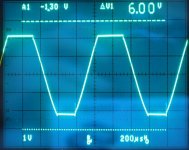
Yes, its possible and it is a little sticky http://www.s-audio.com/forum/download/file.php?id=31&mode=view (20KHz, top is the U2 output, bottom is the amp output). That's why I did not go with even deeper feedback. The clipping behavior is not good but acceptable. I could fix that, but see no simple ways to do that with LM3886. On the other hand if you listen -120dB THD amplifier, it is better to listen before clipping level anyway. I am going to make a clipping indicator, so if it does not blink, you listen the amp in a very low distortion condition for sure.jcx said:I like seeing composite/high loop gain amps, but they do face some constraints most people aren’t familiar with
The loop gain is “Conditionally Nyquist Stable” – the phase shift exceeds 180 degrees near 10-200 KHz where the loop gain is as low as ~ +20 dB – this indicates the possibility of nonlinear large signal oscillation in the event of clipping or slew rate limiting (I believe the plot's "0 degree" line is actually 180 degrees of loop gain phase shift- just an effect of the choice of AC Vsource test polarity) For any amp using this type of higher order loop gain the actual amp’s clipping performance ‘scope shots are mandatory to see possible oscillation bursts or "sticky" clipping recovery
You are right. So if you have such a bad LM3886, you have 2 options, change it, or reduce the R22 resistor (or change the U2 compensation). Personnaly I did not see any of LM3886 with GBW < 8MHz yet.A limit on small signal stability is the uncertainty in the loop gain – for the fast small signal op amps with local feedbacks this is not too big an issue but the LM3886 loop gain intercept and phase margin over production lot variations and loads could require larger margins to be successful over many units: 40 degrees phase margin and <10 dB upper gain margin would be considered by most control engineers as somewhat risky with the LM3886 GBW spec of 2 MHz min to 8 MHz typ ( a 12 dB range)
also the lm3886 recommended min gain of 10 suggests that a loop gain intercept of greater than 200 KHz isn't a safe design with worst case parts
Sorry, hope this should work http://www.vegalab.ru/forum/attachment.php?attachmentid=22039&d=1192665399 .the link to refernce doesn't seem right to me - maybe is was a dynamic link - care to put the reference info in a post?
Yewen J. High-precision composite op-amps.
Electronics & Wireless World, vol.93, no.1612, Feb. 1987, pp. 227-8.
Circuit Boards
After talking to Nick, I think his plans are to make a run of boards in the future. He mentioned 50 boards, but that is a very small run. Hopefully he will have enough interested people to run off more.
He GAVE me some of his prototype boards. The design is top notch. Includes regs for main B+, and output protection circuitry with mechanical relay, and a led power point.. I need to chase down the components to build, looks like a real winner.
Nick put a lot of effort into this, not just the active circuitry, but the power supplies, and output relay are all very well thought out.
The four layer boards are also a step up for me, double sided have been SOTA.
Hope to be up and running in the next couple weeks.
George
Prototype boards work fine, so I did some minor changes and fixes, and decided to order final version. I have ordered 30pcs for now. So please let me know if you are interested.
Here you can find schematics, BOM, and full PCB layout.
http://www.s-audio.com/forum/viewtopic.php?f=2&t=5
Here you can find schematics, BOM, and full PCB layout.
http://www.s-audio.com/forum/viewtopic.php?f=2&t=5
This is great news.
In this version have you altered the compensation to improve clipping behaviour?
In this version have you altered the compensation to improve clipping behaviour?
Mykola said:Prototype boards work fine, so I did some minor changes and fixes, and decided to order final version. I have ordered 30pcs for now. So please let me know if you are interested.
Here you can find schematics, BOM, and full PCB layout.
http://www.s-audio.com/forum/viewtopic.php?f=2&t=5
Here is clip with no load. Input is 1kHz sin.al2002 said:This is great news.
In this version have you altered the compensation to improve clipping behaviour?
Attachments
") So I plan to fix it in another projects, with no LM3886.
So I plan to fix it in another projects, with no LM3886.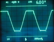
- Status
- This old topic is closed. If you want to reopen this topic, contact a moderator using the "Report Post" button.
- Home
- Amplifiers
- Chip Amps
- My ZD-50 ultralow distortion chipamp.