Your values are fine as long as you put the feedback ground on the other side of the 10R resistor. The 470p should go to the input side of the 2.2R as well, but the 22k resistor should stay where it is. And 2.2R is a more optimal value than 10R. This resistor needs to be set so that CMRR is best across the input pot volume range. Use 1% resistors.
There is a way to get very high CMRR, but your source impedance must be almost zero, and if you use a pot you get 0 CMRR through most of the range. It's too complicated to recall from memory so most advice about it ends up being wrong.
There is a way to get very high CMRR, but your source impedance must be almost zero, and if you use a pot you get 0 CMRR through most of the range. It's too complicated to recall from memory so most advice about it ends up being wrong.
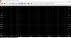
Thanks for the chart! That's incredibly helpful.... but it all depends what you are trying to stop getting in though. It should cover potential problems from RF in most cases. This is your filter response.
So, db0 at 100khz with 470n, then 2n2 would be close to the audio band without harm? Down by 0 at 21khz?
It has a flaw in that the gain divider isn't right if lower voltage is used--the values must be adapted for current too. For example, at +-20vdc there's some fair indications 47k and 1k5 might be a good idea, but I haven't checked closely. And, at +-15vdc, the datasheet schema starts to work reasonably.It looks pretty standard...
Also there's at least 6 'varieties' of 'lm1875' including 3 rail splitters (2 of which don't work for music) and 2 lower power amplifiers (TDA2030 and NEC, which require lower gain and lower voltage). My schematic works for the real thing and one of the other. So, that would be a third of the time if the indicated voltage was used, and I doubt it. The odds aren't looking too good.
However a 'standard' might be possible at lower voltage--surely not more than +-18vdc. Then everyone would build it at higher voltage anyway.
That explains the 'Turbo II' and 'Turbo III' schematics. They're the contingency plan for having built at higher voltage.
I've been doing some research and it seems that the costs of a groundlift are higher than anticipated, and, to me, that means the item in the wrong locale, was the groundlift resistor. Is that about right?Your values are fine as long as you put the feedback ground on the other side of the 10R resistor. The 470p should go to the input side of the 2.2R as well, but the 22k resistor should stay where it is. And 2.2R is a more optimal value than 10R....
When there is an RC series to an amplifier input, the R should make contact with the amplifier input. Like this (links to one of Mooly's 3 options) P.S. looks like you want 1k2 in your filter, or a slightly smaller RF cap.Referring to the schematic below, borrowed from post #693:Should the R6/C8 network be in front or behind C1?
Last edited:
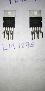
Please anyone tell me if it's original or fake one. I am waiting to make an amp with this for my home. Thanks! ! :-)[/QUOTE said:My chips are authentic, well , the one from left is not the original STMicroelectronics but it was made by http://www.unisonic.com.tw/datasheet/TDA2050.pdf.
The one on the right is lm1875 made by Texas Instruments(National was bought in 2011 by TI). I do believe that your chips are not authentic.
Attachments
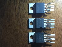
Real LM1875's are available, but that does vary by market. The fakes do make amplifiers, and the closest match is the TDA2030 datasheet (especially flyback diodes and lower voltage).Has LM1875 gone out of Production or it's still there? I'm sending a picture of LM1875 as attachment. Please anyone tell me if it's original or fake one. I am waiting to make an amp with this for my home. Thanks! !")
Good choices for transformer include:
12-0-12
13.5-0-13.5
14-0-14
With those chips use conservative voltage and the TDA2030 datasheet (pretend that you're building a TDA2030 amplifier). The odds are good at getting a 10 watt amplifier with a very pretty sound.
For speaker protection, you may want a dc protection circuit board, or the option of large capacitance (4400u~6600u) series to speaker negative. With the smaller core, the amp shouldn't use 4 ohm speakers; however, it can work nicely with 8 ohm speakers.
This is useful, everyday, as a daily listening amp; however, it isn't the thing to use for a loud party because the core is too small for huge current. The same could be said of the real LM1875. The difference between a 10 watt amp versus a 21 watt amp is just 3db at the speaker.
Is the unpopulated board the pcb only or the pcb with parts unpopulated?
Board only.
There are a few good designs available with gerber files for the LM3886. All you need to do is send the files to have the boards made.
Hi Mark,
Could you please spot a couple of those designs?
Thank you.
Evangelos
I've been doing some research and it seems that the costs of a groundlift are higher than anticipated, and, to me, that means the item in the wrong locale, was the groundlift resistor. Is that about right?
The benefits are spoiled by the fact that for best performance you need a source with zero output impedance. If you had that, then you wouldn't even need the groundlift resistor. But then if you need an input pot you have to compromise. You add the groundlift resistor, which half works, and there is a middle ground between allowing too much ground current and allowing too much ground voltage, which depends on your source cable shield resistance.
The best compromise is still useful, maybe 6-20db CMRR. And it varies with pot position and input cable. It might be worth it from the numbers but from a circuit point of view it's like getting everything in the buffet mixed together vigorously. It looks simple but it's actually complicated and tricky, and people usually can't even remember how to do it right.
Yes, the groundlift is like throwing a wrench in the works, resulting in some RCR's (like high-esr bad caps) instead of the desired RC's. For the hookup that was recommended, the only patch I could think of was to throw a token 100n resistor at the problem. For treble quality at the 200u, choices include bypass routing (seen earlier) bypass the groundlift resistor with a cap, a DC Tracker (yuk!) or bypass the groundlift resistor with a solid copper wire.The benefits are spoiled by the fact that for best performance you need a source with zero output impedance. ...
Attachments
Last edited:
It was also necessary to look reasonable as well as work, so there's this (attached).
To be done is a graph that shows different input and gain dividers as well as fine tuned stability components corresponding to different voltage (and use). However, if you have the 18-0-18 transformer handy, this works. It may be somewhat party oriented, which is unusual for the 5-pin chip amp.
To be done is a graph that shows different input and gain dividers as well as fine tuned stability components corresponding to different voltage (and use). However, if you have the 18-0-18 transformer handy, this works. It may be somewhat party oriented, which is unusual for the 5-pin chip amp.
Attachments
Rod Elliot's design (and board) seem excellent for authentic LM1875.
Single Chip 25W Amplifier (Project 72)
I would like to see that with C3=100uF, C7=220uF, C8=220uF, and +-17VDC
(using your 12-0-12vac 64va transformer at your power supply board).
If small speakers + EQ, use C1=1uF polyester.
Bonus: Here's the tone section Hi-Fi Preamplifier
Single Chip 25W Amplifier (Project 72)
An externally hosted image should be here but it was not working when we last tested it.
I would like to see that with C3=100uF, C7=220uF, C8=220uF, and +-17VDC
(using your 12-0-12vac 64va transformer at your power supply board).
If small speakers + EQ, use C1=1uF polyester.
Bonus: Here's the tone section Hi-Fi Preamplifier
I used a vero-build. Start at post #24.Daniel, can you share a pcb version for your lm1875 turbo III? thanks
Be sure to compare the resistor values on the TurboIII with an orthodox build. It is good to see which you like better. There are also quite a few varieties in 5-pin chips, some of which need the high gain, and some don't. The label on front, really doesn't provide a clue about which chip is inside.
- Home
- Amplifiers
- Chip Amps
- Beginner's Gainclone, HiFi LM1875, The Amplifier Board