first, you need to ensure that no ground loop on your implementation.
second, you might want to try the followings.
can you verify you rail voltages (+) (0) and (0) (-) are the same? as you have (+) (0) (-) rails, different value, for example 25 v (+ rail) and 24.7 v (- rail) will probably cause hum. please make sure the rail voltages prior to connecting your amp.
have you tried removing the 50K pot while using the pre-amp and keeping R1? or turn the pot to the max while volume is controlled from your pre-amp? if hum is still heard, you probably want to try smaller value for pot, like 10k or 20k.
if hum is still there, the problem might be somewhere else.
However then I decided to use the preouts of my headphone amp and then just the 50k potentiometer all the way up because I figured that it was the same as having a 50kohm shunt resistor and shouldn't hurt anything. I still hear a hum even when the preamp is at the absolute minimum.
first, you need to ensure that no ground loop on your implementation.
second, you might want to try the followings.
can you verify you rail voltages (+) (0) and (0) (-) are the same? as you have (+) (0) (-) rails, different value, for example 25 v (+ rail) and 24.7 v (- rail) will probably cause hum. please make sure the rail voltages prior to connecting your amp.
have you tried removing the 50K pot while using the pre-amp and keeping R1? or turn the pot to the max while volume is controlled from your pre-amp? if hum is still heard, you probably want to try smaller value for pot, like 10k or 20k.
if hum is still there, the problem might be somewhere else.
On a reasonably built amplifier, 0.3v rail offset does not cause a hum. You will be well served to search in a different place for that trouble. Mine do not ever hum.
Hello.
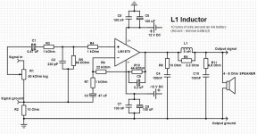
I have mixed the Daniel beginners amp with details from other designs with the LM1875.
Would someone kindly tell me, if there are any major issues with the design?
For information, R3, R4 and C2 are for general stabilization and against radiofrequency interference/oscillation.
I have chosen 12 V power-supply since it's gonna be a PC-amp and one of the design-criterias is, it must fit in a small box I have at hand. (SIC!) So no big trafos.
There will be a Carlos-style powersupply. Dual mono build with 2 pcs. 9V ac windings, each rated at 1,66 Ampere.
https://www.flickr.com/photos/52442906@N02/34016646256/in/dateposted-public/
Last edited:
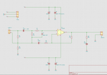
I have been going over the posts in this thread, which has caused me to modify the design.
Specifically, I have implemented the Dr. Cherry LF phase modification, which also should allow the 50 kOhm potmeter, allowing a damping-factor > 5 for the input-signal.
Hope for a comment or two.
https://www.flickr.com/photos/52442906@N02/33238946604/in/dateposted-public/
I found an eBay seller, that provides a print with all components for 1 LM1875 for 2.50 USD, free postage and ordered 4 pcs. The LM1875 are used but are tested OK, according to seller.
Here's an evaluation on Youtube.
https://www.youtube.com/watch?v=d9O7oZEYALI
Otc,
try adding an R+C across the speaker terminals.
Reduce R9 across the inductor and use the removed portion as the resistor value in the R+C.
The lower value for R9 will damp the ringing in the output inductor, L1. Try 3r3 (3 off 10r in parallel), or 5r (2off 10r in parallel).
The R+C becomes 6r8, or 5r + 100nF
This has the added benefit of slightly reducing the RF that gets injected from the speaker cables.
Please attach your pics rather than use a remote server.
Last edited:
AndrewT,
Thank You for evaluating the circuit and suggestion of added RF-filtering.
If I understand correctly, that would be like in attachment?
It would be advantageous to use a 20 or maybe even 10 kOhm log pot, in stead of the 50 kOhm? (R1)
Amp will primarily get input from my PC soundcard.
Glad for all comments, as it has proved beneficial over time, for me, to take a few dry-runs, before warming op the soldering-iron.
Ole
Attachments
Last edited:
10k, or 20k or 50k vol pot would all work.
Even with the 50k vol pot and 100pF of cable to the power amp you would have a low pass filter of ~ 1/(2 Pi R C) = 1/(2*3.14*13500*100+220)*10^12 = ~36kHz or about 1dB down @ 20kHz, when the vol pot is at ~-6dB
The 6r8+100nF goes across the amplifier's speaker output terminals, it is not at the amp PCB.
The amp now sees 5r+200nF as the HF loading when no speaker and no cables are attached.
You can now trim R5 to minimise the output offset. Start with a 100k 3/4 turn temporary VR in place of R5, to find an approximate value for R5. Then you can insert a fixed resistor just above that value for R5 and add a big VR to do final trimming. Maybe 82k || (200kVR+270k) which gives you an adjustment range of 63k to 70k
Last edited:
Hello.
I have mixed the Daniel beginners amp with details from other designs with the LM1875.
Would someone kindly tell me, if there are any major issues with the design?
Oh yeah! Voltage! Seems like the datasheet example aimed low, involving a 12+12vac transformer driving the supply. The practical values gets a little different if you aimed high, as I did with an 18+18vac transformer driving the supply. If you wanted the middle ground (if you bought a 15+15vac transformer), then averaging works.
To me, it looks as if you'd have aimed for leveling current differences at the small signal input transistors, between the different published designs, then the best practical examples all look the same. In other words, you'd be well served by coddling the small signal input section, as the primary goal.
Last edited:
I will leave the circuit as is, for a while now.
Will start the PS-design and build.
Then wait for the cheap chinese LM1875's to arrive.
Then assemble, listen and try to get a general idea about which size the C6 and C8 should have. Apart from the National Semiconductor suggestion of 100 uF, there seems to be implementations with somewhat higher values.
The input cap, C1, will be some film-type.
I will return in maybe a month or so from now, with a parts list, etc.
Thank You, Sir.
And Daniel, thanks for Your comment and for starting this thread. It holds invaluable info for me.
")
Will start the PS-design and build.
Then wait for the cheap chinese LM1875's to arrive.
Then assemble, listen and try to get a general idea about which size the C6 and C8 should have. Apart from the National Semiconductor suggestion of 100 uF, there seems to be implementations with somewhat higher values.
The input cap, C1, will be some film-type.
I will return in maybe a month or so from now, with a parts list, etc.
Thank You, Sir.
And Daniel, thanks for Your comment and for starting this thread. It holds invaluable info for me.
Last edited:
C6 & C8 can be any size from 100uF to 1mF
C5 & C7 must be located very close to the chipamp power pins and must have a low loop area back into the Zobel Return and Speaker Return.
C1 must be your input high pass filter.
Be careful that it limits the signal that C3 needs to handle. There should be zero AC voltage across C3, if it is to do it's DC blocking job properly.
C6 & C8 can be any size from 100uF to 1mF
C5 & C7 must be located very close to the chipamp power pins and must have a low loop area back into the Zobel Return and Speaker Return.
C1 must be your input high pass filter.
Be careful that it limits the signal that C3 needs to handle. There should be zero AC voltage across C3, if it is to do it's DC blocking job properly.
Thank, You. I get Your points.
Specifically I read the thread about Prof. Cherry's LF phase-correction in the feedback loop and understand that C1 in my circuit can not go higher in value, it is mandatory in the circuit to cut LF at same or a higher frequency than C3. So will only use value 0,47 uF or maybe smaller, but different types of film-caps.
I suppose the Prof. Cherry phase-correction is audible and not just measurable?
Hi,
I build an LM 1875 mono amp using a Paia.com kit and modifying it according to suggestions in this thread some years ago. I am using an 8 Ohm speaker and my P.S. is 12-0-12. I reviewed pages from the end to about p. 68. I see one discussion about the resistor/inductor network at the amp's output, but I don't understand what purpose this serves. Fill me in, please.
I build an LM 1875 mono amp using a Paia.com kit and modifying it according to suggestions in this thread some years ago. I am using an 8 Ohm speaker and my P.S. is 12-0-12. I reviewed pages from the end to about p. 68. I see one discussion about the resistor/inductor network at the amp's output, but I don't understand what purpose this serves. Fill me in, please.
an amplifier normally has a load. The gain of the amp is stabilised by that load.
Stability margins can change when the load is removed.
At low frequency removing the speakers or removing the speaker cable usually has no effect.
At high frequencies the amplifier is very intolerant of removing the load. So much so that an open output can change the stability margins so much that the amplifier oscillates.
The cure for this risk of reduced stability margins is to add on a load that only operates at high frequency and remains there no matter what is hung on the output.
That HF load is the amplifier Output Zobel. Often you see 10r+100nF but many other values are seen.
Don't omit the output Zobel unless you have proved the amplifier is stable AND has adequate stability margins when the output is left open.
Hi all,
I've been lurking about here for a while now & would like to thank all the contributors to this thread (and others on the board...) for all the excellent information they've provided.
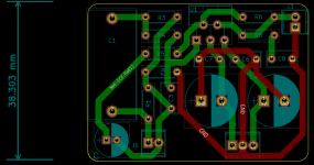
I'm about to have a go at building an LM1875 based amp & would really appreciate it if you guys could have a look at my schematic and board layout & let me know if I'm doing anything particularly stupid.
I've a centre tapped antek toroid (2x15V @ 2.67A) that I'm looking at for the power supply, am I right in thinking that this is going to be not nearly enough to feed two of these things in stereo?
Much appreciated
Jay.
I've been lurking about here for a while now & would like to thank all the contributors to this thread (and others on the board...) for all the excellent information they've provided.
I'm about to have a go at building an LM1875 based amp & would really appreciate it if you guys could have a look at my schematic and board layout & let me know if I'm doing anything particularly stupid.
I've a centre tapped antek toroid (2x15V @ 2.67A) that I'm looking at for the power supply, am I right in thinking that this is going to be not nearly enough to feed two of these things in stereo?
Much appreciated
Jay.
Attachments
Your 2x15Vac 2.67Aac is an 80VA transformer.
That is good enough for between 40W to 80W of total maximum power.
That easily covers a stereo pair of lm1875
Personally I prefer at least 160VA for a power amplifier due to the lower regulation offered and thus the smaller range of voltage between no load and quiescent load and maximum power load.
Your -IN input sees 47k for the DC current .
But you have 23k at the +IN input. Why?
Change that to 47k to match the -IN input and then reduce the input capacitor C1, to 2u2F
I seriously doubt you will be able to hear any difference between an MKT/MKS and an MKP. In my book smaller and cheaper is better.
A physically smaller capacitor here is more tolerant of interference.
C8 (the Zobel route) MUST tie into the decoupling ground between C6 and C7. Do not take it on a meandering route around the PCB. That long route adds inductance/impedance and ruins the performance of the Zobel.
+32dB (40times) is quite a high gain. Do you have a reason for going this high?
Last edited:
- Home
- Amplifiers
- Chip Amps
- Beginner's Gainclone, HiFi LM1875, The Amplifier Board