ServoG: how does the amp sound? ( assuming you have good speakers and source !) ")
If it doesn't sound GREAT then you've done something wrong I guess !
For it's limited power and price it sounds really great.
You said " .....played well....". That isn't the same as "GREAT" !
If it doesn't sound GREAT then you've done something wrong I guess !
For it's limited power and price it sounds really great.
You said " .....played well....". That isn't the same as "GREAT" !
Hey Daniel
I need you help again- it seems I have screwed one of the boards up again
After installing the pots one channel is working good. The other doesn't do anything at a lower volume and crackles really loudly when I turn it up. The music is playing. When it first happened I thought it was the pot so I took it off. The noise was the same. Then I put the pot back on- same thing.
I have looked at this thing for hours comparing it to the one that works as well as this pictures you posted but I can't see anything. The circuit checks out ok. Power at the amp is 24.75 with 0 dc offset at the speaker. I've tried 3 different speakers but it's always the same noise.
sincerely baffled - prezden
Attachments
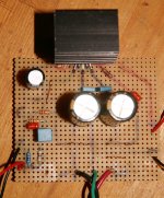
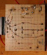
Well, I've stared at it for a good half hour and didn't see anything. But I could not quite identify all of the connections near the little red and blue caps. So, I've got to ask, if you measure between 0v and Pin1 with your ohmmeter, does it do 10K or. . . something else?
Hi Daniel
I have uploaded a shot video to youtube so you can listen to what it sounds like. There is no solder on the heatsink.
Thanks for your help
1875 noise Computer - YouTube
I have uploaded a shot video to youtube so you can listen to what it sounds like. There is no solder on the heatsink.
Thanks for your help
1875 noise Computer - YouTube
That wasn't the slow stead rhythm of the overload sound. Oh, much different!
Be sure to drain the power caps (by applying 50R resistors, not fingers) measure to assure the absence of voltage, and then make really good use of the ohmmeter to compare the board that works against the board that doesn't. Note: Don't modify the working amp board--Just measure it.
You might want to check the feedback and feedback-shunt resistors as well as the nfb-shunt cap and ground--trace around that whole area to see if it matches up with the other board.
If that's all good, then trace all over the input circuit to see if it matches up with the other board.
Next,
Re-heat all solder connections that are on the bad board. Check with some swapping resistors and caps to see if you can "move the problem" preferably away from the amp board--for example, the ohmmeter won't spot bad caps, but you can swap in some different caps, one at a time, to see if they work differently.
and then,
If you've eliminated all of the other possibilities, then a chip might be broken.
Last edited:
The type of copper used there appears to be coated with a clear insulating material (else it would not be so shiny). If, perchance, a solder ball is merely laying atop the copper, it might not have penetrated the clear coating. Applying some Gel Flux and then tinning the copper a bit to be sure the solder really sticks to it, might help assure that a connection exists rather than just the appearance of a connection.
So, while you're re-working the connections, don't forget the Gel Flux.
So, while you're re-working the connections, don't forget the Gel Flux.
Last edited:
If you want the solutions "all together in a single page", take a hard long look at this:
ELECTRONICA / components | projects | applications
Good circuit implementation, "by the book", layout, PCB, finished product pictures, transformer suggestions, even an auxiliary (optional) +/-15V PSU to feed your preamp, if so needed.
The finished PCBs looks like this:
An externally hosted image should be here but it was not working when we last tested it.
EDIT: If you don't want to mess with making your own PCB, this one looks very good:

seems to be available at:
LM1875 /TDA2030 Amplifier Amp board PCB - $9.90 : Enjoy in your hi-fi project, diy tube amp, amplifier diy, amp diy
It's for two LM1875/TDA2030 (I guess TDA2050 should fit there too) and includes the PSU PCB.
All for a claimed $9.90 which sounds reasonable.
I have the XY board actually 2 of them one I will use TDA2050 and the Other LM1875 so I can compare the two. That is once the garage temp drops below 90
If the XY board is built as the designer indicates, then the power circuit will swamp all else and there would be no way to tell if TDA2030/40/50 or LM1875 had more or less merit because of far too much influence from the power circuit due to the mostly absent power decoupling. Rather than sound like either TDA2050 or LM1875, that XY board is most likely to sound like Ebay. Let's just say that the XY board doesn't have a state of the art power circuit.
There's a possible fix!
If one uses an off-board power supply (input DC power to the amplifier board), then the amplifier board's power caps can be 470u per rail and the XY board can probably support Parallel LM1875 or Parallel TDA2050. In that case one board would be monophonic but capable of twice the current. Instead of a cheap gainclone, you'd have a classy 50 watt monobloc amp. It would take two such boards for stereo. But, since you have two boards anyway, the Parallel amp monoblocs prospect looks good!
from reading other threads I had already decided to make a separate power supply set up.
I would also like to parallel or bridge them.
I will want to pick your brain about capacitor out put as my garage speakers roll off at 100hz so there is no reason to send them power down to 50hz or lower, which will just be dissipated as heat.
Those boards are sold by some American importers too and for 10 bucks to my door hard to beat price wise.
I eventually want to add a darlington pair, baby steps as this is all new to me.
I picked up one of these XY boards,
Amazon.com: DROK TDA2030A Digital Stereo Audio Power Amplifier 34W+34W Dual Channel BTL Circuit Amp Board DIY Kit: Electronics
It uses 4 TDA2030A ICs in Btl for 34w peak per channel. Should get here soon. Says AC and DC inputs. What do you think about this?
Amazon.com: DROK TDA2030A Digital Stereo Audio Power Amplifier 34W+34W Dual Channel BTL Circuit Amp Board DIY Kit: Electronics
It uses 4 TDA2030A ICs in Btl for 34w peak per channel. Should get here soon. Says AC and DC inputs. What do you think about this?
I made a mistake, my boards look like this
An externally hosted image should be here but it was not working when we last tested it.
If he has any left in 2 weeks I may grab one myself just to play with.
I have enough TDA 2050 chips to replace those 30's.
What part of Ohio are you in?
North East, In Chardon. I bought it to build my first amp, so not expecting much.
Partially Pre assembled units are great for a 1st time, because you add a power supply and you get music.
I built a 2.1 system from Ebay using a Radio Shack 12.6-0-12.6 2 amp transformer and it works fine.
For heat sinks I used the Radio Shack 486 CPU coolers, I took the fans off the heat sinks and hot glued them about 1 inch away and dropped their voltage down to 10 volts DC that eliminated the noise from the fans and the chips stayed cool. It was also much easier drilling the holes one at a time then attempting to line up 4 holes on a large heat sink.
(which I tried 1st and broke a tap off on the 3rd hole)
I need to take the final pictures and measurements and finish that thread.
I'm not happy with my face plate so I want to make another one.
Hopefully the weather will co operate this weekend.
That is more interesting.I made a mistake, my boards look like this
An externally hosted image should be here but it was not working when we last tested it.
Question:
What cap values does it have for C5, C6, C7, C8?
- Home
- Amplifiers
- Chip Amps
- Beginner's Gainclone, HiFi LM1875, The Amplifier Board