That's a good test to see if the amp is clipping, or if the preamp is clipping itself.
Speaking of clipping, what voltage transformer was used for the amplifier?
P.S.
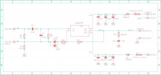
That layout is for a really really warm sound; but, if you'd like it to play clearer, swap C6, C11 for 100uF or larger, with at least 16v spec.
Speaking of clipping, what voltage transformer was used for the amplifier?
P.S.
That layout is for a really really warm sound; but, if you'd like it to play clearer, swap C6, C11 for 100uF or larger, with at least 16v spec.
Thanks you so much !!!.
First I changed the NFB to 860R combine with 20K for Gain 26 but not satisfy cause the sound to be less beautiful. I don't know why
Then i test as your suggest. It's work well then.
First I changed the NFB to 860R combine with 20K for Gain 26 but not satisfy cause the sound to be less beautiful. I don't know why
Then i test as your suggest. It's work well then.
Altering the gain by altering the feedback could cause you big problems with stability. Whilst it can be done, it requires addition of other parts and so is not recommended for a beginner.
The simplest and safest solution would be to add a series resistor to the input to the board. 22k would divide the signal by 2 as it would form a divider with the input bias resistor already present.
Hi,
Cause I guest the LM1785 is fake so I just transformer +-12v only.
I use with preamp DAC AK4490 with Opamp Muse 8920. Really the sound is much strong or loud.
The sound to be better if I use 22k for input.
Cause I want make an audio system 2.1.
I order 2 Pcb as above. one for LM1875 for mid/tweeter and last one TDA2050 for Subwoofer.
All speaker driver come from Peerless. And all is 4ohm also
2 Tweeter for power is 2.5 inch/25W/85db sensitive as documents from peerless give me.
2 Subwoofer I take from Sonos Play 5 Gen 1. 4 inch/30-50W. I don't know the sensitive. this one is for dual sub.
As I saw. sometime we calculate the power amplifier follow larger of driver. And 2.5inch is so more to combine With LM1785 ?
And also I found another amplifier classD 30W, with low NFB. I don't need to take the resistor 22k. It work well too. no more clipping or break sound anymore.
That's a good test to see if the amp is clipping, or if the preamp is clipping itself.
Speaking of clipping, what voltage transformer was used for the amplifier?
P.S.
That layout is for a really really warm sound; but, if you'd like it to play clearer, swap C6, C11 for 100uF or larger, with at least 16v spec.
For standard 2.1 crossover frequency for 150hz with 4 ohm speakers, add a 270uF (or 330uF) capacitor in-series to speaker ground....Cause I guest the LM1785 is fake...I want make an audio system 2.1.... LM1875 for mid/tweeter...And all is 4ohm...
Resources - Crossover Component Selection Guide
Thanks you so much !!!.
First I changed the NFB to 860R combine with 20K for Gain 26 but not satisfy cause the sound to be less beautiful. I don't know why
Then i test as your suggest. It's work well then.
Thats good
 Sometimes simple solutions are all that is needed.
Thanks you !
I have planned filter frequency by use capacitor 220uf for tweeter.
I realized with 4ohm, the amplifier is much hotter than 8ohm very much. So, I think can't use transformer +-15v anymore.
Cause I didn't found the capacitor 22uf, so I swap all to 47uf Nichion audio with 25v for C6,C7,C8, C11,C12,C13. I'll test for C6 & C11 with capacitor 100uf for
Also I'm planing changing C9 & C10 from Wima 1.5uf back to 1.0uf hope for bass is more control.
For standard 2.1 crossover frequency for 150hz with 4 ohm speakers, add a 270uF (or 330uF) capacitor in-series to speaker ground.
Resources - Crossover Component Selection Guide
Sometimes,
I can't understand why they made the preamp is so much strong like that !
If for play with headphone. I can understand. But for amplifier, hmmm.
Cause I'm working on smart speaker, I'm making for prototype. So I'm trying to make best sound as possible. But not easy.
I can't understand why they made the preamp is so much strong like that !
If for play with headphone. I can understand. But for amplifier, hmmm.
Cause I'm working on smart speaker, I'm making for prototype. So I'm trying to make best sound as possible. But not easy.
Thats good
270uF (or 330uF) for 4 ohm midbass. If split-rail amp, the series cap goes ground-side....I have planned filter frequency by use capacitor 220uf for tweeter...
Far smaller for tweeter!
Edit: If there is some concern of Clipping, put capacitors, small capacitors, series to BOTH (+ and -) poles of the tweeter. Personally, I had to add the second cap after a tweeter fire. But, the fix has worked a decade so far.
Last edited:
Hi,
I didn't found the capacitor 270uF yet. So I'll buy also 47uf or 100uf for combine with 220uf current.
Also I changed C9 & C10 to capacitor 1uf. Surprise !!! Bass is less and much control compare to 1.5uf.
And as last time, I used resistor for split input signal become 2. But still much strong. so I change 680R to 1K, and be better and I can set volume to 80% without problem.
I'm finding capacitor 100uf for C6 & C11 for the sound more clear. Even when I'm happy with current sound tone. but let try !
270uF (or 330uF) for 4 ohm midbass. If split-rail amp, the series cap goes ground-side.
Far smaller for tweeter!
Edit: If there is some concern of Clipping, put capacitors, small capacitors, series to BOTH (+ and -) poles of the tweeter. Personally, I had to add the second cap after a tweeter fire. But, the fix has worked a decade so far.
Just another question,
You use small value capacitor series to + and - , the value must use is how much ? Cause I can not buy easy everything, sometime I have to wait to get the accessories. So I always collect all accessories needed then buy in same time.
You use small value capacitor series to + and - , the value must use is how much ? Cause I can not buy easy everything, sometime I have to wait to get the accessories. So I always collect all accessories needed then buy in same time.
270uF (or 330uF) for 4 ohm midbass. If split-rail amp, the series cap goes ground-side.
Far smaller for tweeter!
Edit: If there is some concern of Clipping, put capacitors, small capacitors, series to BOTH (+ and -) poles of the tweeter. Personally, I had to add the second cap after a tweeter fire. But, the fix has worked a decade so far.
Use the RC calculator to predict it. RC Low Pass Filter Calculator...Also I changed C9 & C10 to capacitor 1uf. Surprise !!! Bass is less and much control compare to 1.5uf....
I like their frequency chart.
Hi Daniel
Is the schematic at post #1 still your best choice regarding sound quality for the LM1875 chip amp?
I have made one channel this way, and I think it sounds great.
Before finishing channel number 2, it would be nice to hear, if you have improved the schematic since 2013.
Regards Kurt
Is the schematic at post #1 still your best choice regarding sound quality for the LM1875 chip amp?
I have made one channel this way, and I think it sounds great.
Before finishing channel number 2, it would be nice to hear, if you have improved the schematic since 2013.
Regards Kurt

Hi,
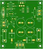
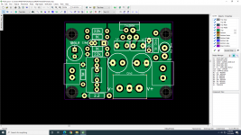
It might help some of the members. Please let me know if there is an error.
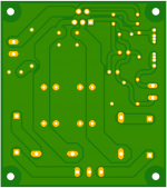
Single-sided board
Size: Width 69.52mm x Length 79.09mm
Thank you
It might help some of the members. Please let me know if there is an error.
Single-sided board
Size: Width 69.52mm x Length 79.09mm
Thank you
Attachments
If installed at speaker ground of a stereo build, two speakers can share the protector.
Hello,
I would like to make a stereo speaker protection for my amp, want to make sure if I understand it correctly?
It should look like this on negative speaker side?
An externally hosted image should be here but it was not working when we last tested it.
As I understand it takes a lot of capacitance, about 20 000uf?
Mindaugas
why single sided board?Hi,
It might help some of the members. Please let me know if there is an error.
Single-sided board
Size: Width 69.52mm x Length 79.09mm
Thank you
My version is 5.5cmx4cm.
Attachments
- Home
- Amplifiers
- Chip Amps
- Beginner's Gainclone, HiFi LM1875, The Amplifier Board