I think that 1 of KBU1004 / KBU1005 (fork shaped rectifier) and two pair of Nichicon's compact series capacitors, 35v 2200uf (4400uF per each rail), will shrink that power supply size down to less than 2 inches square.
The original design for the amplifier itself, was much smaller. It was only expanded for easier soldering and easier documentation.
Smaller original. . .
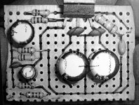
Here's a photo of the original so that you can see its tiny layout.
At some point after it won a local contest, then I notice that the order of the two resistors (lower left), is mixed up.
The 1M was supposed to have made a load upon the cable (but it didn't do that in this smaller original in the photograph below). However, it (the 1M resistor) may either be omitted or simply added to the input cable's connection point (from input + to input-).
The photo also shows a capacitor at position CIN (the big one at the upper left); however, that's unnecessary unless DC offset is high. Since the new design (at this post) has very low DC offset, then you "probably" don't need cap CIN within the NFB.
And, the photo shows a zobel at the speaker output. A more "compact" location for the speaker zobel (that resistor and capacitor at the far right side) would be "at" the speaker output terminals of the enclosure, or it may be omitted.
So, with a few small changes, the amplifier board itself can be made as small as a human thumb.
Have fun!
The original design for the amplifier itself, was much smaller. It was only expanded for easier soldering and easier documentation.
Smaller original. . .
Here's a photo of the original so that you can see its tiny layout.
At some point after it won a local contest, then I notice that the order of the two resistors (lower left), is mixed up.
The 1M was supposed to have made a load upon the cable (but it didn't do that in this smaller original in the photograph below). However, it (the 1M resistor) may either be omitted or simply added to the input cable's connection point (from input + to input-).
The photo also shows a capacitor at position CIN (the big one at the upper left); however, that's unnecessary unless DC offset is high. Since the new design (at this post) has very low DC offset, then you "probably" don't need cap CIN within the NFB.
And, the photo shows a zobel at the speaker output. A more "compact" location for the speaker zobel (that resistor and capacitor at the far right side) would be "at" the speaker output terminals of the enclosure, or it may be omitted.
So, with a few small changes, the amplifier board itself can be made as small as a human thumb.
Have fun!
Attachments
Ah! I've remembered! One reason that the suggested power supply is so large (eight caps, making 8800uF per each rail), is that the transformer requirements are then smaller / not as crucial.
So, do bear in mind:
Large power supply = less requirements for transformer.
Smaller power supply = needs larger transformer.
And,
Large power supply = works for stereo, works for dual mono, works for monoblocs, works for surround amp--got all the bases covered.
Smaller power supply = okay for "dual mono" or monoblocs with pair of 1A transformers. EDIT2: The catch is that if a stereo amp is used with a half-size power supply, then the minimum transformer size requirement gets up around 3 ampers (quite large size transfomer).
Edit: May I suggest transformer shopping first, before considering "shrinking" the power supply.
Copyright
I had a question arrive as to the copyright status of this amplifier design. Here it is.
That statement declares copyright and then provides for anybody to use the design on this thread, as long as it is for diy, non-profit use.
Here are some exceptions to the non-profit status, and these exceptions may also use the design for profit in the form of complete, handbuilt, amplifiers:
1). Educational institutions, schools, trade-schools, universities, and colleges, may use the design for educational purposes, but may not sell "kit" form except to students enrolled at same facility.
2). Devore Audio
3). CommonSense Audio
4). All of the contributors on this thread who made posts prior (previously) to this post.
Here are some exceptions to the non-profit status, and these exceptions may also use the design for profit in the form of complete, handbuilt, amplifiers and also in "kit" form:
1). Peter Daniel, Audiosector
2). FidelityForce
3). Brian Bell, Chipamp.com
The seven exceptions above may also use the design and its schematic for profitable usage in the form of complete, handbuilt, amplifiers. The rights for the design and its schematic may not be transferred or sold. There are no additional rights provided unless expressly stated. A unique prior art: A lot of features were packed into this amplifier design, mainly towards supporting greater-than-usual varieties of music sources and speakers. The component values used are unique to it, and the performance vs. price ratio is also unique. The declaration of copyright and the notarized printout, hold it as a prior art, so that the DIY community may continue to build this design and enjoy it for diy, non-profit use.
I had a question arrive as to the copyright status of this amplifier design. Here it is.
danielwritesbac said:Before we get much further, I need to say:
The design on this thread, and its schematic, are free for diy, non-profit use.
That statement declares copyright and then provides for anybody to use the design on this thread, as long as it is for diy, non-profit use.
Here are some exceptions to the non-profit status, and these exceptions may also use the design for profit in the form of complete, handbuilt, amplifiers:
1). Educational institutions, schools, trade-schools, universities, and colleges, may use the design for educational purposes, but may not sell "kit" form except to students enrolled at same facility.
2). Devore Audio
3). CommonSense Audio
4). All of the contributors on this thread who made posts prior (previously) to this post.
Here are some exceptions to the non-profit status, and these exceptions may also use the design for profit in the form of complete, handbuilt, amplifiers and also in "kit" form:
1). Peter Daniel, Audiosector
2). FidelityForce
3). Brian Bell, Chipamp.com
The seven exceptions above may also use the design and its schematic for profitable usage in the form of complete, handbuilt, amplifiers. The rights for the design and its schematic may not be transferred or sold. There are no additional rights provided unless expressly stated. A unique prior art: A lot of features were packed into this amplifier design, mainly towards supporting greater-than-usual varieties of music sources and speakers. The component values used are unique to it, and the performance vs. price ratio is also unique. The declaration of copyright and the notarized printout, hold it as a prior art, so that the DIY community may continue to build this design and enjoy it for diy, non-profit use.
Enclosure
The next step. Enclosure!!
I'm a terrible carpenter. So, this may take a while. I'd like an enclosure design that someone can build at home, with basic tools, at a speedy timeframe, and the result is still pretty. That's going to take some new education for me.
Any help?
P.S. I'm going bicycle touring across Iowa next week, but will return short after that.
Resistors, Options, and MP3
In response to some recent emails:
MP3 Player:
Some mp3 players are too weak to push the amp with our design's gain setting, so here is more gain. For reference, popular MP3 players can begin the compression artifacts of clipping at just 60% of their maximum output setting.
NFB ground leg = 560R (instead of 620R)
Input series = OMIT 470R (or use 3.3R)
Input load = 10k* (instead of 15k)
*A metal film resistor could be a preferable choice for your new 10k input load, because the all-band performance of metal film is nicely efficient at correctly shunting away high frequency noise.
This new setting will increase the gain and it will cut the DC offset in half.
The NFB of 27k (we didn't change that) with 560R (instead of 620R) is a maximal gain setting, according to National Semiconductor.
In testing, this has worked nicely for helping weaker MP3 players. Enjoy!
Parts Suggestions
Daniel,
I am considering building the LM1875 amp featured in this thread to power a Pioneer B20 or Fostex FE206 based speaker. First, thanks a ton for all of the great info you have presented here. It is terrific.
Do you have any specific part suggestions? I'm trying to sort through all of the available parts (which seem to be limitless). I was just curious if you had any specific brand/type of resistors/capacitors/etc. that you found to be of good quality and price for use in the LM1875 based amp.
For the PSU, I'm considering
http://www.diyaudio.com/forums/attachment.php?s=&postid=1518101&stamp=1211538575
which I believe you posted. I have the same question here, any suggested parts?
Finally, are input caps required on the LM1875? I notice some LM3875 based GC amps don't use them (see http://diyaudioprojects.com/Chip/Synergy-LM3875-Gainclone/)
Thanks,
Patrick
Re: Parts Suggestions
Thanks for the compliment!
This design, like Audiosector chip amps, is a "mixed coupled" design, not a fully AC coupled design. Mine uses (requires!) either a capacitor at the input or whatever Peter Daniel's recommend is for an input isolation transfomer--either can block DC at the input.
If this amplifier http://diyaudioprojects.com/Chip/Synergy-LM3875-Gainclone/doesn't require the cap, that's because there is a cap in the output of the preamplifier and it never uses any other source; not even by accident; especially not by accident, as that accident would be a speaker fire. Mine, or Audiosector, or 47 Labs, or Chipamp.com could do the exact same thing. Please don't omit the DC blocking cap (or optional transformer) from the input. The risks aren't acceptable (in my opinion).
With any chip amp, it is especially important to measure DC offset before! connecting a speaker.
Okay, that lecture is done. Sorry if it may have been rude, but that might be worthwhile if it prevents trouble.
This design is a "values only" effort, and so it has already been hardened against the effects of component variance--so there's no need for excess spending.
Some spendy benefit is possible, at your option:
*You could purchase high quality 470uF capacitors for the amplifier board, and these are used along with the 100nF (0.1uF) that have already been shown at the amplifier board.
*You could also purchase a metal film 15k, or preferably, a 10k resistor for your Input Load because the all-band performance of metal film is desirable in a shunt role (and nowhere else in my design). The 10k option reduces DC offset.
*You could purchase whatever is typically used for Audiosector amplifier's DC input block (Blackgate "N"), and then you should omit the optional 470R compensation resistor.
*You should use 1w (or better) strength resistors for speaker zobel and also 1w strength for power supply board bleeder resistors.
-Except for those, the amplifier design is optimized for ordinary components.
The power supply design schematic, that you referenced, has a generic value for snubbing the rectifier, but you should use one that's a better match for your specified transformer, like the chart of http://www.diyaudio.com/forums/showthread.php?postid=1588619#post1588619 Please don't omit the bleeder resistors from the schematic. Their place is shown (far above) in the photo, here at post 59. They are also shown in the several CarlosFM power supply design schematics.
The power supply schematic referenced here at post 59, has no need of botique components because it was optimized for ordinary components. I cannot discuss a physical power supply because of liability, but we can talk about a schematic all you like. For help with a physical power supply, please see that division of diyaudio.com or your local electrical specialist.
Another consideration for full range speakers is Audio Nirvana at www.commonsenseaudio.com.
Other ways to employ full range drivers are demonstrated in the famous wideband speakers like http://www.harbeth.co.uk/uk/index.php?section=products&page=monitor40.1&model=Monitor 40.1 and http://www.partsexpress.com/projectshowcase/indexn.cfm?project=MagnaCumLaude
whereby the wideband (full range) driver does the majority of the work, but doesn't have to rattle the whizzer when you want bass.
EDIT: Open ended questions make for very big answers. Most of the questions asked are already answered in either this thread or in the Audiosector threads. Read some more, stay safe, and then have fun.
pclements said:Daniel,
I am considering building the LM1875 amp featured in this thread to power a Pioneer B20 or Fostex FE206 based speaker. First, thanks a ton for all of the great info you have presented here. It is terrific.
Do you have any specific part suggestions? I'm trying to sort through all of the available parts (which seem to be limitless). I was just curious if you had any specific brand/type of resistors/capacitors/etc. that you found to be of good quality and price for use in the LM1875 based amp.
For the PSU, I'm considering
http://www.diyaudio.com/forums/attachment.php?s=&postid=1518101&stamp=1211538575
which I believe you posted. I have the same question here, any suggested parts?
Finally, are input caps required on the LM1875? I notice some LM3875 based GC amps don't use them (see http://diyaudioprojects.com/Chip/Synergy-LM3875-Gainclone/)
Thanks,
Patrick
Thanks for the compliment!
This design, like Audiosector chip amps, is a "mixed coupled" design, not a fully AC coupled design. Mine uses (requires!) either a capacitor at the input or whatever Peter Daniel's recommend is for an input isolation transfomer--either can block DC at the input.
If this amplifier http://diyaudioprojects.com/Chip/Synergy-LM3875-Gainclone/doesn't require the cap, that's because there is a cap in the output of the preamplifier and it never uses any other source; not even by accident; especially not by accident, as that accident would be a speaker fire. Mine, or Audiosector, or 47 Labs, or Chipamp.com could do the exact same thing. Please don't omit the DC blocking cap (or optional transformer) from the input. The risks aren't acceptable (in my opinion).
With any chip amp, it is especially important to measure DC offset before! connecting a speaker.
Okay, that lecture is done. Sorry if it may have been rude, but that might be worthwhile if it prevents trouble.
This design is a "values only" effort, and so it has already been hardened against the effects of component variance--so there's no need for excess spending.
Some spendy benefit is possible, at your option:
*You could purchase high quality 470uF capacitors for the amplifier board, and these are used along with the 100nF (0.1uF) that have already been shown at the amplifier board.
*You could also purchase a metal film 15k, or preferably, a 10k resistor for your Input Load because the all-band performance of metal film is desirable in a shunt role (and nowhere else in my design). The 10k option reduces DC offset.
*You could purchase whatever is typically used for Audiosector amplifier's DC input block (Blackgate "N"), and then you should omit the optional 470R compensation resistor.
*You should use 1w (or better) strength resistors for speaker zobel and also 1w strength for power supply board bleeder resistors.
-Except for those, the amplifier design is optimized for ordinary components.
The power supply design schematic, that you referenced, has a generic value for snubbing the rectifier, but you should use one that's a better match for your specified transformer, like the chart of http://www.diyaudio.com/forums/showthread.php?postid=1588619#post1588619 Please don't omit the bleeder resistors from the schematic. Their place is shown (far above) in the photo, here at post 59. They are also shown in the several CarlosFM power supply design schematics.
The power supply schematic referenced here at post 59, has no need of botique components because it was optimized for ordinary components. I cannot discuss a physical power supply because of liability, but we can talk about a schematic all you like. For help with a physical power supply, please see that division of diyaudio.com or your local electrical specialist.
Another consideration for full range speakers is Audio Nirvana at www.commonsenseaudio.com.
Other ways to employ full range drivers are demonstrated in the famous wideband speakers like http://www.harbeth.co.uk/uk/index.php?section=products&page=monitor40.1&model=Monitor 40.1 and http://www.partsexpress.com/projectshowcase/indexn.cfm?project=MagnaCumLaude
whereby the wideband (full range) driver does the majority of the work, but doesn't have to rattle the whizzer when you want bass.
EDIT: Open ended questions make for very big answers. Most of the questions asked are already answered in either this thread or in the Audiosector threads. Read some more, stay safe, and then have fun.
AndrewT said:Hi,
for your first chipamp use an AC coupled version.. . .
My apologies that I couldn't publish a fully ac coupled amplifier that could compete with the popular DC coupled kits. The best I could do was absolutely insist on an input filter cap to block DC at the input, and I also mention to check DC offset. The resulting "mixed coupled" amplifier isn't inferior--Its competitive.
When possible, I'll change it to fully AC coupled; however, that is not yet competitive within the hi-fi genre. I do keep asking for help. . .
AndrewT said:. . . Use good quality cheap components.. . .
Oh yes!!
There's no need to cause the requirement for botique components--and I didn't.
whoooow...By daniel: I cannot discuss a physical power supply because of liability

I thought the DIY'er assumed responsibility for building a project. I would think that we CAN discuss it
as long as we post a disclaimer warning of the dangers
associated with actually building it.
Many projects here at DIYaudio deal with VERY deadly DC
voltages (one flash and your ash) but we still discuss
them.(and post plans for them)
OS
BTW, I think national semiconductor is the copyright owner
for this amp /base design...I CAN sell them commercially
or in any manner I wish, according to natl.semi (they want
to sell more chips).
ostripper said:whoooow...
I thought the DIY'er assumed responsibility for building a project. I would think that we CAN discuss it
as long as we post a disclaimer warning of the dangers
associated with actually building it.
Many projects here at DIYaudio deal with VERY deadly DC
voltages (one flash and your ash) but we still discuss
them.
OS
Conveniently, the name of this thread is "Beginner's Gainclone, HiFi LM1875, The Amplifier Board" and in-depth discussions of other circuit boards is off topic.
I have read that the chipamp forum of diyaudio.com does contain a permanent thread offering power supply directives. That is only an observation.
I wouldn't touch that topic with an eleven and a half foot double-insulated pole--because you know where it would. . .
ostripper said:. . . BTW, I think national semiconductor is the copyright owner
for this amp /base design...I CAN sell them commercially
or in any manner I wish, according to natl.semi (they want
to sell more chips).
If you'll notice, its not the base design as listed in National Semiconductor's PDF. The base design's usage under its copyright is included within the purchase price of the amplifier chip.
A design based on a chip can still be a unique design. So, copyright was declared in order to protect the diy community. In this case, the copyright declaration prevents anyone from restricting (capturing, preventing) the usage of this particular amplifier design.
EDIT: National Semiconductor is the sole exception (of course).
If you'd like to mass produce mine, you need only change a few component values and also make a layout change because that would make a different design. Have fun! It a nice amp.
Do please be careful around voltage, amperage, and high capacitance. In that combination, the lower voltage is still quite powerful.
Lately, I've been working on 30w versions that run cold. Old-fashioned AB amplifiers with linear power supplies can be surprisingly efficient when they're tuned towards "only audio." The whole thing, transformer included, is barely bigger than a coffee cup.
Lately, I've been working on 30w versions that run cold. Old-fashioned AB amplifiers with linear power supplies can be surprisingly efficient when they're tuned towards "only audio." The whole thing, transformer included, is barely bigger than a coffee cup.
Hi,
Here is a good way to start, has anyone tried this kit.
http://cgi.ebay.com/Power-Amplifier...photoQQcmdZViewItemQQ_trksidZp1742.m153.l1262
Regards,
Eric
Here is a good way to start, has anyone tried this kit.
http://cgi.ebay.com/Power-Amplifier...photoQQcmdZViewItemQQ_trksidZp1742.m153.l1262
Regards,
Eric
ostripper said:At +- 30v you could reasonably avoid shock hazard unless you DIY'ed in the bathtub...
I've got permanent burn scars from a 36 volt battery from when I first got into diy in my teens (and I most certainly was not in the bathtub). Any power source deserves respect as given the right set of unfortunate circumstances, it doesn't take much to do considerable and long lasting harm.
Thank you for the wonderful thread -- I am well on my way to building my first GC using this LM1875 design. I do have a few questions, and I apologize for bringing back a year old thread.
The first and most daunting question I have is about the power supply board. I plan on using the Avel 250VA 18V+18V toroidal transformer in stereo mode with one PS board. This is the suggested transformer from chipamp.com. While I have read the DD powersupply page and it has been wonderfully helpful, especially with safety and warnings, I am having trouble visualizing the end product. Dan, post #59 is extremely helpful. Would the Avel transformer and your powersupply work appropriately without modification? The transformer is the only part of great expense in the project, and I would like to get it right the first time around.
Is there a concise thread that covers the basic construction of the powersupply? The sticky thread is over 500 posts long, covering far too many details for me to keep straight.
Thank you!
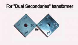
Yes, that transformer is workable and the 18+18 vac 160va version will work just as well. Here is a clue for the means to connect it.
This unit replaces the single rectifier seen elsewhere in this thread.
This is a photo of a dual rectifier, suitable for connecting a dual secondaries transformer. Each secondary winding "powers up" one bridge rectifier. See photo. It is a pair of 10a rated, clearly marked, bridge rectifiers. Imagine flashlight batteries that are within a two-cell flashlight when you look at this photo.
Attachments
Here is an optional transformer that can power two of LM1875 amplifiers for a Stereo build. The price is lower and the performance is excellent.
Allied - 6K274VBR - Allied Electronics
This is a center tap transformer, so it uses only one bridge rectifier.
A big 20a one piece bridge rectifier unit is generally recommendable for chip amplifier stereo builds.
With an EI core transformer, the cabinet layout is slightly more critical. Use the heatsink as a wall/fence/barrier to shield small signal areas away from the transformer. This layout is common to most classic amplifiers. Or, simply use a larger enclosure and increase the space between (distance away from) small signal areas (potentiometer, chip, rca jacks).
An externally hosted image should be here but it was not working when we last tested it.
Allied - 6K274VBR - Allied Electronics
This is a center tap transformer, so it uses only one bridge rectifier.
A big 20a one piece bridge rectifier unit is generally recommendable for chip amplifier stereo builds.
With an EI core transformer, the cabinet layout is slightly more critical. Use the heatsink as a wall/fence/barrier to shield small signal areas away from the transformer. This layout is common to most classic amplifiers. Or, simply use a larger enclosure and increase the space between (distance away from) small signal areas (potentiometer, chip, rca jacks).
- Home
- Amplifiers
- Chip Amps
- Beginner's Gainclone, HiFi LM1875, The Amplifier Board