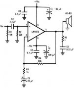
I'd suggest you to build the version from the datasheet. Even with generic components, it still sounds good. My first built was using generic component with 12-0-12 transformer and I was happy for about a year before making a new one with better components. The higher the voltage, the more power you get from the amp and at the same time, more heat. Just be prepared. ")
Just measure before soldering the components. After this success, then you can try to modify the circuit.
Cheers!
Just measure before soldering the components. After this success, then you can try to modify the circuit.
Cheers!
Please avoid using the LM1875. It is too fragile for that approach.There is a place that makes custom toroids for stock prices. So tell me 19.7V or any ood rating, it will be custom after all, lets exploit it
I'd suggest you to build the version from the datasheet. Even with generic components, it still sounds good. My first built was using generic component with 12-0-12 transformer and I was happy for about a year before making a new one with better components. The higher the voltage, the more power you get from the amp and at the same time, more heat. Just be prepared.
Just measure before soldering the components. After this success, then you can try to modify the circuit.
Cheers!
Thats a relief thanks. Which power circuit did you use?
Please avoid using the LM1875. It is too fragile for that approach.
Would 2x18V custom be OK?
Between chipamp.com PSU and the one you suggested in first post(serial caps) which one is better?
"♦ 36va*0.67=24 watts, which is perfect; however, we might want to adapt to dual secondaries and twin bridge rectifiers to maximize the little 1 ampere transformer. Use a mains fuse."
36VA or 160VA transformer?
The small array is a better performer; however, the chipamp.com supply is more compact and lower cost.Between chipamp.com PSU and the one you suggested in first post(serial caps) which one is better?
So, 2x18v 36va (monoblocs--you'll need a transformer and a power supply board per each LM1875 chip that way), orWould 2x18V custom be OK? "♦ 36va*0.67=24 watts, which is perfect; however, we might want to adapt to dual secondaries and twin bridge rectifiers to maximize the little 1 ampere transformer. Use a mains fuse." 36VA or 160VA transformer?
2x15v 60va is fine for a stereo amp.
2x12v 96va is also okay for stereo amp (and uses the datasheet schematic)
160va is too much because it makes breakage more likely.
So, I have a question:
Do you have 4 ohm speakers or 8 ohm speakers or 16 ohm speakers?
If you can tell me that (the workload), I could get closer to saying what transformer to use with your amp.
Last edited:
Range for transformer is 2x14 to 2x16, and up to 3 amperes.
That can be used with either the datasheet schematic or this: http://www.diyaudio.com/forums/atta...875-amplifier-board-lm1875_daniel_2013-ii.gif It does show the fuses.
That can be used with either the datasheet schematic or this: http://www.diyaudio.com/forums/atta...875-amplifier-board-lm1875_daniel_2013-ii.gif It does show the fuses.
My newest project is a stereo amp with LM675 (sister to LM1875).
It is using a 12.5-0-12.5 2a center tap transformer (25vct*2a=50va).
The power supply is one prefab bridge rectifier and a pair of 3300uF each rail.
It is a prospect very much like Radio Shack's STA19 http://www.radiomuseum.org/r/radioshack_realistic_sta_19_31_1975.html . . . which had used the little 5 pin chip amps.
Last edited:
100nF is not a snubber.mine is using..........., snubber 100 nf at each pair of bridge legs, two 2200 uF of nichicon fine gold ............
100nF is an oscillator when combined with the inductance of the attaching leads/wires/traces. Especially when low esr capacitors are used.
Something funny happened. I have been trying to find a transformer anywhere, couldn't find, so i gave up. Looked for Class-D amps that run from walwart and laptop psu etc. They are cheap too. Just when i decided to buy it, i found a compatible transformer i need on the same store Here:
Yuan Jing Audio - R-Core Transformer 65VA, INPUT: AC 0-115V-230V, OUTPUT: AC 0-18V x 2 - USD $34.30 - 65VA
Now i am trying to decide between buying a 50w+50w Class-D amp and building the LM1875 amp. I wanted to start this as a DIY project and buying a finished board seems like cheating. And i guess LM1875 will sound better right? LM1875 will be much more expensive though. 2 x 35$ transformer and already double the price of the Class-D board. With class-d, i only need the board, i have many compatible good quality DC PSU's at hand. I am leaning towards Class-D board. I will make do with it for a time then upgrade to something like parallel 86 or other moderate size projects.
There is a very good page about class-d amps. Its weird i never saw it so far:
TPA3116D2 Boards - diyAudio
Anyway...
Thank you all for your help. I will use the information on a bigger project in the future
Here:Yuan Jing Audio - R-Core Transformer 65VA, INPUT: AC 0-115V-230V, OUTPUT: AC 0-18V x 2 - USD $34.30 - 65VA
Now i am trying to decide between buying a 50w+50w Class-D amp and building the LM1875 amp. I wanted to start this as a DIY project and buying a finished board seems like cheating. And i guess LM1875 will sound better right? LM1875 will be much more expensive though. 2 x 35$ transformer and already double the price of the Class-D board. With class-d, i only need the board, i have many compatible good quality DC PSU's at hand. I am leaning towards Class-D board. I will make do with it for a time then upgrade to something like parallel 86 or other moderate size projects.
There is a very good page about class-d amps. Its weird i never saw it so far:
TPA3116D2 Boards - diyAudio
Anyway...
Thank you all for your help. I will use the information on a bigger project in the future
We might could run a stereo amp on ONE such transformer. Two bridge rectifiers, snubbed with 10n little green polyester dip cap, and then you'd have the target voltage reasonably.
That voltage is slightly too high for the datasheet generic/sample schematic.
At that higher voltage, either of my designs will do well.
For the Turbo style, you can experiment with a smaller value feedback resistor.
The other is native to that voltage and doesn't need any further mods.
That voltage is slightly too high for the datasheet generic/sample schematic.
At that higher voltage, either of my designs will do well.
For the Turbo style, you can experiment with a smaller value feedback resistor.
The other is native to that voltage and doesn't need any further mods.
I love this post. Thank you for saving us from chasing a mystery problem like that one.100nF is not a snubber.
100nF is an oscillator when combined with the inductance of the attaching leads/wires/traces. Especially when low esr capacitors are used.
Some 33n ceramic disc or ceramic x7r seem to work okay along with the low esr electrolytic caps. I've had trouble if using larger values except for when the little bypass cap's quality was so poor that it worked like a really good RC. Might as well save a few cents and go for the ceramic disc, right?

memleket, I have deleted all your duplicate posts in this thread. Your posts don't appear immediately because you are still under moderation and all your posts have to be approved first.
Your question has been answered here,
http://www.diyaudio.com/forums/chip-amps/260251-lm1875-gainclone-input-cap-size.html#post4379005
- Home
- Amplifiers
- Chip Amps
- Beginner's Gainclone, HiFi LM1875, The Amplifier Board