I've searched for info on this to no avail, but excuse me if it's been discussed ad nasuem.
I'm planning on building a MLTL for a set of Fostex full range (from 4.5 - 8 inches, undecided).
I was thinking about using an LM1875 in 'current source mode' to drive it a la Nelson Pass.
It's my understanding that to do so you put the speaker in the feedback loop with a resistor (znom/10) to ground.
My question is, given the wide bandwidth this would allow, will there be stability issues with doing this? Is this an oscillation magnet or otherwise going to be a nightmare?
I was going to put the chip in the speaker cabinet somehow to make an active speaker.
Has anyone done this successfully? Any hints you can share?
Any/all feedback is apprecaited. Cheers.
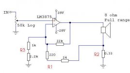
Well, here is my version of mix-mode amp. I think it will drive Fostex speakers just fine. You can tune it with R1, R2 and R3 for your needs.
Don't forget-R2 is dissipating some power, so calculate the wattage you'll need.
Changing the resistors you can set the sound you like.For example-changing
R3 from 4,7k to 1k and the mids and hights
starts to approach ordinary GC sound.
You must try for yourself and find the right combination.
I've tried different values for the resistors and found the
best results with values:
R1=220 to 330 ohm
R2=0.22 to 0.33ohm
R3=1k to 4.7k
Attachments
A combination of reading a review of the Lizard Wizard (or something like that) -- a 3875 transconductance amp) -- and getting a chance to listen to one of Duo's tranconductance amps has me very interested in this.
Duo's amp is ~15w, has an output impedance > 1M ohm, and was not designed with speakers in mind (it was designed to drive a CRT), We tried it on 3 different Fostex... on the FE108eS in Aiko it was bloated in the bass. Not near enuff control. With the Fonkens it sounded really good but just a bit fat in the bottom (some might like that). Driving the µFonken just plonked on top of the Fonkens it was superb (but Duo reports that the same with the speaker ssitting on the desk either side of his computer monitor it wasn't so good)
He promises a variable Z transconductance amp designed with audio in mind... you turn a knob to dial the amp in for your speaker & room.
dave
Interesting. My fostex experience is pretty limited (limited to smaller drivers) so I couldn't imagine having too much bass. I guess it will be necessary to adjust depending upon the driver and enclosure.
So anyone around have thoughts on stability?
Every gainclone I've built osciallated as some point. One was input/output coupling and another was a misplaced zobel, so they were both manageable. I am hoping that opening up the bandwidth doesn't make it worse.
For the record, I've cooked at least 6 LM's and almost every line level opamp project I've put together went crazy. I seem to be a magnet for out of control opamps.
I had no problem with stability. Like I said, you can adjust the sound to your leaking. This amp suppose to go well with fullrange drivers with lightweight membranes helping them in the bottom region. Check Pass Labs site - there should be an article about amps driving fullrange drivers.
Of course, ordinary loudspeakers might sound bloomy with such amp because of the damping factor.
Regards;
Of course, ordinary loudspeakers might sound bloomy with such amp because of the damping factor.
Regards;
This would be a true transconductance amp, Zout=infinity. It requires stabilization means, to counter the inductive effect of the voice coil. You must make the speaker load look resistive for HF, and you must obey the minimum gain requirement for the chip (or use noise gain compensation for lower gains).m@ said:I was thinking about using an LM1875 in 'current source mode' to drive it a la Nelson Pass.
It's my understanding that to do so you put the speaker in the feedback loop with a resistor (znom/10) to ground.
Details see:
http://apex.cirrus.com/en/pubs/appNote/Apex_AN13U_C.pdf
- Klaus
KSTR,
Thanks for the link, I'll check it out.
Igla,
I read that Pass article and that's exacly why I'm doing it - an elegant way to eq a full range driver, regardless of the other benefits. Ideally I would use a copy of his F2 (single ended, zero feedback) but since this will be an active design, I don't want to have to deal with the power and dissipation requirements.
The other direction I was thinking about going was to use a class-D amp, but for me that would require using a t-amp or something similar. I would have to use a series resistance in that case and it's seem pointless to me to use a high efficiency amp and then burn up power in a resistor.
One point I forgot to mention:
Some drivers do exhibit chaotic behaviour when driven with a true current source:
http://ip565bfb2a.direct-adsl.nl/articles/timphany/paper_aes117th_jr.pdf
I don't know if high efficiency fullrange drivers are prone to this.
Therefore, I may suggest that you follow Igla's way of driving, which seems to be quite similar to a proposal from Rod Elliott:
http://sound.westhost.com/project56.htm
I have been using this for chipamp-based guitar amps -- set to about 4 ohms Zout -- and it worked fine (guitar speakers hate low-Z drive).
- Klaus
Re: Re: LM1875 as transconductance amp for Fostex
Hi Klaus!
Here's one I wish I hadn't missed, back when I was doing one of these for the first time. It's called a "comprehensive study" of both the Howland and the Improved-Howland current pumps (like Fig 7 in the nice AN-13u, for which you provided a link, above). It also includes a small section about the Howland Integrator (aka 'DeBoo Integrator'), and also one about the Differential Integrator, which I like for DC Servos. It's by Bob Pease, and even includes some interesting history:
http://www.national.com/an/AN/AN-1515.pdf
I've been designing a small circuit with an Improved-Howland inside of a feedback loop (which completely linearizes the R vs I response of an LED/LDR analog optoisolator, by the way!), but just now found that appnote, 'accidentally'.
Even though it can be a bit 'finicky', sometimes, I really like the Improved-Howland's performance. Is there some reason why an Improved-Howland type of VCCS would not be preferred, with the speaker as Rload (or maybe even as Rsense, with a resistor for Rload??)? [I admit I've never really thought about using one for an audio amplifier, although I do use one with a push-pull booster just after the opamp, in a 2.25-Watt current or voltage staircase waveform base/gate driver, for my curve tracer, which operates with transition rates from 60 Hz to 22 kHz (but with edge times of a only a few microseconds, which, actually, were purposely made to be much slower than they could have been.). It works extremely well.]
IIRC, there was an article in EDN (I think it was), maybe not long ago, about using a Howland-type topology as an audio power amplifier.
I still kind of like the idea of using a very good opamp for the actual Howland part, and putting the power amp just after the opamp, but still inside the feedback loops, as a current-dumping 'power booster'. For chipamps that have a minimum stable gain, maybe a resistive divider (e.g. 20:1) could be used between the opamp and the chipamp 'booster' circuitry.
KSTR said:This would be a true transconductance amp, Zout=infinity. It requires stabilization means, to counter the inductive effect of the voice coil. You must make the speaker load look resistive for HF, and you must obey the minimum gain requirement for the chip (or use noise gain compensation for lower gains).
Details see:
http://apex.cirrus.com/en/pubs/appNote/Apex_AN13U_C.pdf
- Klaus
Hi Klaus!
Here's one I wish I hadn't missed, back when I was doing one of these for the first time. It's called a "comprehensive study" of both the Howland and the Improved-Howland current pumps (like Fig 7 in the nice AN-13u, for which you provided a link, above). It also includes a small section about the Howland Integrator (aka 'DeBoo Integrator'), and also one about the Differential Integrator, which I like for DC Servos. It's by Bob Pease, and even includes some interesting history:
http://www.national.com/an/AN/AN-1515.pdf
I've been designing a small circuit with an Improved-Howland inside of a feedback loop (which completely linearizes the R vs I response of an LED/LDR analog optoisolator, by the way!), but just now found that appnote, 'accidentally'.
Even though it can be a bit 'finicky', sometimes, I really like the Improved-Howland's performance. Is there some reason why an Improved-Howland type of VCCS would not be preferred, with the speaker as Rload (or maybe even as Rsense, with a resistor for Rload??)? [I admit I've never really thought about using one for an audio amplifier, although I do use one with a push-pull booster just after the opamp, in a 2.25-Watt current or voltage staircase waveform base/gate driver, for my curve tracer, which operates with transition rates from 60 Hz to 22 kHz (but with edge times of a only a few microseconds, which, actually, were purposely made to be much slower than they could have been.). It works extremely well.]
IIRC, there was an article in EDN (I think it was), maybe not long ago, about using a Howland-type topology as an audio power amplifier.
I still kind of like the idea of using a very good opamp for the actual Howland part, and putting the power amp just after the opamp, but still inside the feedback loops, as a current-dumping 'power booster'. For chipamps that have a minimum stable gain, maybe a resistive divider (e.g. 20:1) could be used between the opamp and the chipamp 'booster' circuitry.
Hi Tom,gootee said:It's by Bob Pease, and even includes some interesting history:
http://www.national.com/an/AN/AN-1515.pdf
Thanks for this link, seems to be rather new stuff (Jan 29, 2008). I'll certainly give a read.
Maybe you know of Mauro Penesa's RevC, discussed here? It's a somewhat degenerated Howland'ed LM3886 (Zout<Infininty), inside a feedback loop of a LM318. Has some reputation, but it is still a conventional voltage output amp. I think the Howland's main point is the "free" output reference, outside the actual loop. And the trimming possibility, allows for negative Zout also, plus it has a wider range of adjustable Zout vs Gain compared to the simpler Elliott circuit. The compensation issues are similar to in-the-loop (floating load) config.Even though it can be a bit 'finicky', sometimes, I really like the Improved-Howland's performance. Is there some reason why an Improved-Howland type of VCCS would not be preferred, with the speaker as Rload (or maybe even as Rsense, with a resistor for Rload??)? [I admit I've never really thought about using one for an audio amplifier...]
[...]
IIRC, there was an article in EDN (I think it was), maybe not long ago, about using a Howland-type topology as an audio power amplifier.
I think for impoved DC/LF specs this might work out well. OTOH, the in-loop buffer determines HF-stability as much as the control amp and usually the buffer must be completely stable on its own before closing the loop. This will restrict the overall level of performance for HF to that of the buffer, the opamp being (supposedly) way faster (and hence must be heavily compensated).I still kind of like the idea of using a very good opamp for the actual Howland part, and putting the power amp just after the opamp, but still inside the feedback loops, as a current-dumping 'power booster'. For chipamps that have a minimum stable gain, maybe a resistive divider (e.g. 20:1) could be used between the opamp and the chipamp 'booster' circuitry.
My preferred article on Howlands and other current pumps is another one from Apex engineers, published 1992 in the EDN magazine:
http://apex.cirrus.com/en/pubs/whitePaper/199210-Apex-Versatile_current_source_circuits.pdf
(The merger of Apex and Cirrus is getting on my nerves, all the old links to the excellent Apex papers run into the void now, those IT guys don't seem to get it handled to provide for proper redirection... arrghhh).
- Klaus
Hello guys, it took me a while to get to this.
I have the design set out for a variable impedance amplifier (practically from zero to infinity, infinitely variable).
The concept behind this is to be able to critically damp a driver, or speaker system for that matter.
The cause of flabby bass is the under-damping of a driver... So for those thinking you'll get more/better bass with this, thing again. This only works to a small extent, after which things get extremely out of hand and the bass just sounds terrible, colored, and out of control.
The first concept amps I've built showed me what transconductance amps can do for driving speakers, but one must design the speaker entirely around the high impedance amp in order for this to work. I've put together a number of speakers so far, all of which have been open-baffle with very strange suspension/damping modifications. The most important mod I did was to reduce Fs below the range for which the speaker was use, which isn't too abnormal anyway.
Having variable output impedance will allow the amplifier to give its benefits to any speaker, but without the worry of under-damping.
I'll get back here with results when planet10 and I have done some listening.
KSTR said:Hi Tom,
Thanks for this link, seems to be rather new stuff (Jan 29, 2008). I'll certainly give a read.
I didn't even notice the recent date. 'Maybe' THAT'S why I didn't find it before!
Maybe you know of Mauro Penesa's RevC, discussed here? It's a somewhat degenerated Howland'ed LM3886 (Zout<Infininty), inside a feedback loop of a LM318. Has some reputation, but it is still a conventional voltage output amp. I think the Howland's main point is the "free" output reference, outside the actual loop. And the trimming possibility, allows for negative Zout also, plus it has a wider range of adjustable Zout vs Gain compared to the simpler Elliott circuit. The compensation issues are similar to in-the-loop (floating load) config.
Yes. I did read most of that thread. Looks pretty good but I never built one. (I like to design my own.
And yes, the Howland-type circuits are quite versatile. They have been extremely helpful in solving some real-world design problems, for me. I now consider them to be 'good friends to have'.I think for impoved DC/LF specs this might work out well. OTOH, the in-loop buffer determines HF-stability as much as the control amp and usually the buffer must be completely stable on its own before closing the loop. This will restrict the overall level of performance for HF to that of the buffer, the opamp being (supposedly) way faster (and hence must be heavily compensated).
Absolutely. In the case I mentioned, I had to have at least 150 mA of output current available, at up to + and - 15 volts. Back then, I knew relatively much less than I do now, even, and putting the little BD139/BD140 push-pull amplifier inside the Howland loops as a buffer just seemed like the obvious thing to do. In simulations, it looked like I needed a very fast opamp. But I ended up using an OP275 (22 V/us max, I think, with FET inputs) in the real circuit and it was 'good-enough'. From the 3-Ohm current-sense resistor, I had a 100 Ohm series resistor before the load (i.e. an unknown transistor's base or gate pin), such that the max needed output current could just be reached, without much headroom, when a typical load was present. It needed 33 pF between the opamp's + and - input pins, and just 2.2 pF from the opamp's output pin to neg input pin. Feedback resistors were on the order of a few hundred Ohms, while the opamp inputs' resistors were on the order of 10K.
My preferred article on Howlands and other current pumps is another one from Apex engineers, published 1992 in the EDN magazine:
http://apex.cirrus.com/en/pubs/whitePaper/199210-Apex-Versatile_current_source_circuits.pdf
(The merger of Apex and Cirrus is getting on my nerves, all the old links to the excellent Apex papers run into the void now, those IT guys don't seem to get it handled to provide for proper redirection... arrghhh).
- Klaus [/B]
THANK YOU, very much, for that link, Klaus! I don't know how I didn't find that one, before, which is a bit scary. That looks like it might help me a whole lot, with my current project, which uses an Improved-Howland VCCS, used for uni-polar output only, driving the LEDs of two analog optoisolators in series, where the compensation looks like it is critical, at least when the circuit is configured to have a relatively-fast dynamic response and a very wide range.
Are you still looking for a transconductance amp after all these years? Goto Headphone Systems and look for Antoinel.
schematif.pdf >>> Page not found
Thanks
R.C.
- Status
- This old topic is closed. If you want to reopen this topic, contact a moderator using the "Report Post" button.
- Home
- Amplifiers
- Chip Amps
- LM1875 as transconductance amp for Fostex