Transformer Wiring
Hello, I'm new to the forum.
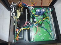
I recently bought a spring Type Z5500 subwoofer only with all the electronics inside. Problem is, the toroidal transformer cables were cut and there are no clear pictures to show proper wiring, nor there are any schematics.
This is what I've managed to figure out, though I could be totally wrong!
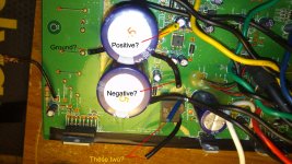
Toroidal transformer has 7 wires, black/white are 120v ac.
Yellow/black/Orange - yellow and orange go to the bridge rectifier, right? with the black wire being ground? Does this make sense?
Blue/blue - I have no idea where these go, there is a small bridge rectifier on the main board, where a blue wire goes... there is also a black wire, but... I have no idea where the other blue wire goes?
Any help would be much appreciated, as I want to resurrect this beauty!
Hello, I'm new to the forum.
I recently bought a spring Type Z5500 subwoofer only with all the electronics inside. Problem is, the toroidal transformer cables were cut and there are no clear pictures to show proper wiring, nor there are any schematics.
This is what I've managed to figure out, though I could be totally wrong!
Toroidal transformer has 7 wires, black/white are 120v ac.
Yellow/black/Orange - yellow and orange go to the bridge rectifier, right? with the black wire being ground? Does this make sense?
Blue/blue - I have no idea where these go, there is a small bridge rectifier on the main board, where a blue wire goes... there is also a black wire, but... I have no idea where the other blue wire goes?
An externally hosted image should be here but it was not working when we last tested it.
Any help would be much appreciated, as I want to resurrect this beauty!
Attachments
I think I found something about the wiring
Okay, I think I found a picture I can work with, picture is not mine, so I'm borrowing it from rjaii.
As far as I can see, the two blue wires coming from the toroidal transformer are connected to the two blue and black wires from the board (small bridge rectifier) via a couple of bell cap connectors, is this right?
The only question I might have is... the black wire is ground? I probably need to look at some power supply schematics to get the info on that one...
Any comments?")
Okay, I think I found a picture I can work with, picture is not mine, so I'm borrowing it from rjaii.
As far as I can see, the two blue wires coming from the toroidal transformer are connected to the two blue and black wires from the board (small bridge rectifier) via a couple of bell cap connectors, is this right?
The only question I might have is... the black wire is ground? I probably need to look at some power supply schematics to get the info on that one...
Any comments?
Attachments
i have a complete working spring clip type z5500 connected to my computer. today I picked up a standalone powered subwoofer at a yardsale. I'm interested in connecting the powered subwoofer to the existing z5500 so I have even more bass. What pinouts or wires do I need to tap into in the z5500 to send an output signal to the input of the standalone powered subwoofer
Does anyone get speaker thump or pop when turning your system on or off?
I'm using a pod bypass cable I bought on Ebay a couple years back connected to an Asus AT3IONT motherboard, and whenever I turn the system of or shutdown I get a thump/pop from the system. I'm about to check if all channels by unplugging each audio plug and power cycling.
I just found the diagram in this thread for adding pots to the channels, and will be doing so. Mainly for bass, with out the pod there's no way to easily pump the bass up.
Maybe the voltage regulator will silence the amp during powering on/off cycles, or it seems I need to add capacitors somewhere to absorb the signal coming from the motherboard during powering on/off.
I've been playing with hardware and software settings to do with sound the past couple hours, so I don't think I can resolve this with a setting.
I'm putting this system together to sell, and this is the last tidbit to wrap up. I don't want the new owner getting it and hearing powering on/off noise.
Thanks!
Wow, the pots are an absolute must!
I have another set of Z5500's with the control pod and connected it, along with the freshly replaced subwoofer (el cheapo Amazon Pyle 10" DVC 4ohm), really rocks!
So I'm starting to formulate a plan for this system to really tie it together as the system I'll be selling it as.
Will +5v turn the amp on?
hello, I am new to the forum and I live in Brazil.
I have a home that the Z5500 control pad is shutting down, so I need to adapt the P2 cable therein, the PID it is the R020 which wiring diagram that the most right?
Already tried the taught in post # 485 put without the voltage regulator, I will test now with the regulator.
Has anyone tested this solution? https://www.youtube.com/watch?v=UAaKV4yEuK8
hugs,
Rudolph
Thank you EVERYBODY for you contributions to this thread since 2007. Truly inspirational!
I too have a pre-636, spring-clip version Z5500 with dead control pod. My goal was to create a bypass cable going from my computer sound card straight to the sub, with no internal sub mod, and still having 5.1 surround, yes all six speakers working, including center and sub working perfectly, and independently, just like they should.
The posts that helped me the most were knexkid, Toffmonster, fluxarc , Sstevensn72 , and the final big puzzle piece, foodbag, the key being the 7805 voltage regulator, and not directly grounding pin 8. Thank you all for your help!
My bypass works perfectly, all six speakers. Front Left, Front Right, Rear Left, Rear Right, Center, and Sub all working, tested independantly using Realtek test screen where you can select each speaker and hear it play. I also added pots to control volume, just as everyone else recommended. I recommend too, as it is very loud. Here is youtube video of my bypass in action.
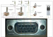
The only thing that I noticed was my D-Sub female connector numbering is backwards from what this forum suggests. I've attached my schematics for both no-pot, and with-pots. You can see my D-Sub connector with embossed numbers. They are definitely backwards, but this works great!
I hope this post helps someone like all of the others did for me. Good Luck!
hello, I tested the schema without potentiometer post # 485 with the voltage regulator and gave sound in front, behind and under, give sound was missing in the central, and this same standard?
tanks,
Rudolph
POD K.O. & pin 10 doesn't suply 8v
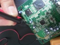
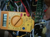
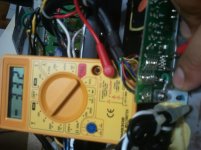
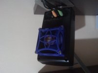
Hi, two days ago my loved z 5500 said good-bye . it happened restarting when i turned on the system. well, It seemed was a temperature problem, so i install a fan, like it can see in some webs. For that, i soldered fan as we can see in the image (ok, is not image there, xD but as can see in the 4 image, there i soldered the fan). the voltage at this moment was 7,8 aprox. Well, 0ne day gone on that invention. Now, the POD is dead, and the voltage fan is 0. I has wanted to test the voltage in the sub and pin 10 don't suply 8 v, now 3.4 aprox.
i don't know what happend, but i want to know if it's possible to do the bypass even though the voltage in pin 10 is weird.
i hope so, i like so much my z5500
thanks for all! (and sorry for my english xDD)
Hi, two days ago my loved z 5500 said good-bye
. it happened restarting when i turned on the system. well, It seemed was a temperature problem, so i install a fan, like it can see in some webs. For that, i soldered fan as we can see in the image (ok, is not image there, xD but as can see in the 4 image, there i soldered the fan). the voltage at this moment was 7,8 aprox. Well, 0ne day gone on that invention. Now, the POD is dead, and the voltage fan is 0. I has wanted to test the voltage in the sub and pin 10 don't suply 8 v, now 3.4 aprox.i don't know what happend, but i want to know if it's possible to do the bypass even though the voltage in pin 10 is weird.
i hope so, i like so much my z5500
thanks for all! (and sorry for my english xDD)
Attachments
Last edited:
Hi, two days ago my loved z 5500 said good-bye
i don't know what happend, but i want to know if it's possible to do the bypass even though the voltage in pin 10 is weird.
i hope so, i like so much my z5500
thanks for all! (and sorry for my english xDD)
err.. i quoted
i'm sorry. Edit. yeah! i spend some time probing the system (only sub and central) and at this moment, sub works properly xD, besides, i has been reading this post and i have to say: thanks a lot for your works and feedbacks, really now is easy to make the work.
my system's a R714, i think i don't need to use +-5v for ground, so my problem with low v in pin 10 has desapeared... maybe. in some days i'll recive new wires and other stuff, i think i buy too some pots and make a POD mod with the old case.
thank to all, german, english, russian... whoever makes it possible that i could do this.
See ya friends.
Last edited:
What a fantastic thread. Thanks Undertone for starting it all those years ago, and thanks to all the other contributors. Great work.
I have an early spring clip version, R533, I got in non working condition about 2 months ago. The original owner had already gotten an out of warranty, discounted replacement, from Logitech and this unit was just taking up space so he gave it to me. The pod was totally dead. No stand by, no power, no display. And no sound. I did some research and discovered this was an extremely common issue with this system. So I opened the pod and was surprised to see that both the front and back sides of the circuit board in the pod were covered with what appeared to be white, powdery corrosion. I got out a fine, stiff brush and some 97% denatured alcohol and went to town on the board. When I got it looking like new I used my blow dryer to get it thoroughly dry and then plugged it in and turned it on. It worked! And I discovered why he liked this system so much. And now, about 6 weeks later, after I've grown to really like these speakers, the pod died again. I had just started Quake2 (one of my favorites) and turned to ask my son something. When I turned back the pod was in stand by mode, red led on the power button. I didn't remember turning it off so I grabbed the remote and hit the power button to turn it back on and it went completely off. No red or blue led, no display, and no sound.
Now I'm looking at replacing the pod with this mod using Przano's layout. But I would still like to use the pod. Does anyone have any idea what could have caused my unit to die the way it did? Any specific things I should look for? I'm a long-time vintage Hi-Fi enthusiast so I have the tools and know how to use them.
Thanks,
Rick
P.S. Hoping this thread is still alive.
err.. i quoted
Edit. yeah! i spend some time probing the system (only sub and central) and at this moment, sub works properly xD, besides, i has been reading this post and i have to say: thanks a lot for your works and feedbacks, really now is easy to make the work.
my system's a R714, i think i don't need to use +-5v for ground, so my problem with low v in pin 10 has desapeared... maybe. in some days i'll recive new wires and other stuff, i think i buy too some pots and make a POD mod with the old case.
thank to all, german, english, russian... whoever makes it possible that i could do this.
See ya friends.
Same problem!!! Question: Is it possible to use another power source to replace this +8v?
PID 512 working again
Hi,
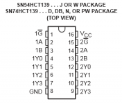
After investing another 3 hours and studying the logic of the HTC139, I was able to fix some of my previous problems. Opposed to previous solutions for my PID 512 I had to hook up pin 7 to +5V and not connect pin 8 at all. This way, amplification is normal and no distortion occurs on the front channels. The only thing I didn't manage to get working without a workaround was the center channel. So I still had to connect +8V to center enable on the subwoofer board. I also added a switch between +5V and pin 7. I'll also add a LED before and after the switch to display main power and "power on".
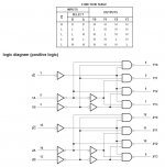
Pin 7 and pin 8 are connected to 1A and 1B of the HTC139. 1G is always low. Y1 and Y3 are controlling "power on" and "center on". So with the right combination of signals on pin 7 and pin 8 you're able to switch on the amp. Feel free to hook up +5 or GND to those pins to experiment. Due to the HTC139 you won't do no harm.
The pin-out of my amp is:
1: Rear Right (brown)
2: Subwoofer (grey)
3: Left Right (yellow-black)
4: Center (blue-black)
5: Left Front (yellow)
6: not connected
7: Power ON (blue)
8: Mute (white)
9: Right Front (violett)
10: +8V (red)
11: ground (green)
12: ? (white-black)
13: ground (green)
14: +18V (red-black)
15: -18V (black)
Hi,
After investing another 3 hours and studying the logic of the HTC139, I was able to fix some of my previous problems. Opposed to previous solutions for my PID 512 I had to hook up pin 7 to +5V and not connect pin 8 at all. This way, amplification is normal and no distortion occurs on the front channels. The only thing I didn't manage to get working without a workaround was the center channel. So I still had to connect +8V to center enable on the subwoofer board. I also added a switch between +5V and pin 7. I'll also add a LED before and after the switch to display main power and "power on".
Pin 7 and pin 8 are connected to 1A and 1B of the HTC139. 1G is always low. Y1 and Y3 are controlling "power on" and "center on". So with the right combination of signals on pin 7 and pin 8 you're able to switch on the amp. Feel free to hook up +5 or GND to those pins to experiment. Due to the HTC139 you won't do no harm.
The pin-out of my amp is:
1: Rear Right (brown)
2: Subwoofer (grey)
3: Left Right (yellow-black)
4: Center (blue-black)
5: Left Front (yellow)
6: not connected
7: Power ON (blue)
8: Mute (white)
9: Right Front (violett)
10: +8V (red)
11: ground (green)
12: ? (white-black)
13: ground (green)
14: +18V (red-black)
15: -18V (black)
Attachments
Neuweiler,
I'm planning on building this pod bypass and I like the changes you've made. They look like they make sense for my system with PID R533. Question, when you say
One more thing, will you be posting your LED additions here too (please)?
Thanks,
Rick
P.S. Glad someone is still keeping this thread alive
I'm planning on building this pod bypass and I like the changes you've made. They look like they make sense for my system with PID R533. Question, when you say
did you fix this with the yellow jumper you show in one of your images? Also, I seem to remember some posters mentioning grounding or ungrounding pin 6 to mute the system. Have you looked into that?The only thing I didn't manage to get working without a workaround was the center channel. So I still had to connect +8V to center enable on the subwoofer board
One more thing, will you be posting your LED additions here too (please)?
Thanks,
Rick
P.S. Glad someone is still keeping this thread alive
Yes, the yellow cable in the picture on the left is used to enable the center speaker.Question, when you say did you fix this with the yellow jumper you show in one of your images?
I couldn't locate any wire in the original cable which connects to pin 6. But I think pin 8 is mute and if grounded or connected to 5V will mute the system.Also, I seem to remember some posters mentioning grounding or ungrounding pin 6 to mute the system. Have you looked into that?
Glad if it helps someone. The LED's are very easy. If you want a LED to light up as soon as the device has power, connect it to the right side of the switch (in the diagram) and if you want to connect one to light up when it is switched on, connect it on the left side of the switch. Place a 220Ohm resistor in series of the LED connect the other side of the LED to ground. Depending on the color and size of the LED you may have to use a different resistor. (check resistor calculators on the net).One more thing, will you be posting your LED additions here too (please)?
Thanks,
Rick
P.S. Glad someone is still keeping this thread alive
Connect a LED like this
Attachments
Project Completed. Almost. Still a couple of things I plan on adding. I think I can add a mute function by simply connecting pin 8 to 5v+ through a switch. This worked in testing by touching the pin 8 lead to the 5v+ on pin 7 (also on the 8v+ supply on pin 10). I would also like to add a master volume control, but my current project box isn't quite large enough to hold a 6 gang pot. Another thing I would like to add is a headphone jack that will mute the speakers when a headset is plugged in, but I haven't figured that one out. Yet.
Attachments
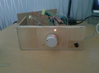
Hello all the people,
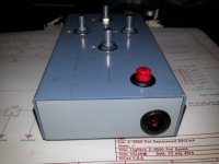
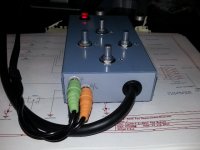
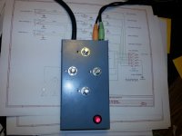
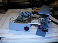
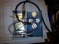
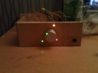
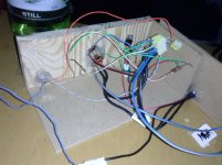
I wanted to share my experience with z5500 without control pod. I stumbled upon logitech z 5500 sub without satellites or control pod. i searched online and immediately stumbled upon this beautiful forum and thread. I found the picture for a bypass cable with pots and vga adapter, lm7805, but all you know this very well. So i made one, and it fired up the sub on my first attempt. It was working perfectly. So i wanted to build like a box for potentiometer and on/off button, led's, so i did. As you can see in pictures...i have to close it but it is finished. Now all is working....but i noticed that when i turn on the sub there is this popping noise you know like POP, the speaker is not protected there are no relays like in ordinary power amps and so on...so this was like a DC pulse, in happens, but it was annoying. Maybe its not good for the speaker maybe it is, i don't know but it was annoying. So i wanted to solve it. Now,
pin 7 and pin 8 are very important for this. pin 7 is Amp on so it turns the amp on and pin 8 is mute. From the diagram mentioned when you get 8v to lm7805 and pin 6 pin 7 and pin 13 are connected to ground as in diagram, lm7805 fires up the amp and the mute is off at the same time so a pulse goes through the speaker and there it is a POP. First i tried connecting capacitors across lm7805 to suck up the spikes but that didn't work. The basic idea is that when pin 7 gets the ground, so to speak, the mute should be active all ready so no pops or whatever on speaker. I noticed that when i connect a resistor and a LED to ground directly from lm7805, pin 7 somehow through this resistor gets grounded and amp is on and +5v to pin 8 makes mute on so no POPs on on or off. Its hard to explain but i will post a diagram. Basically all you need is a resistor from lm7805 directly to ground and amp is on and mute is on and no pops. so then through a switch you can turn off +5v to pin 8 mute is off and speaker is on completely silent. i will post a diagram shortly. But the main idea is to turn on the amp before mute is off. And that happened when i put a resistor directly from +5v on lm7805 directly to ground .
cheers!
Attachments
Me again,
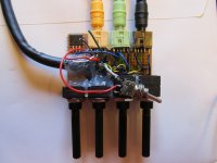
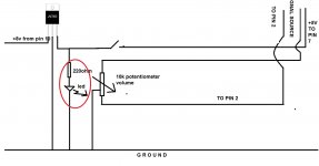
here is the diagram...i left out all the other led's but they are simple to connect. That thing circled in red grounded pin 7 and amp turns on , but at the same time mute is on through pin 8. You can af course lose that LED which is in red circle and leave only the resistor. I can now "this thing in red" connect through a switch so there are 2 switches, one amp on, the other the black one is all ready mute on/off. I don't know why this happened, but now are amp on and mute separated, and there are no POPs on on/off. I think its something in amplifier control board that through a resistor pin7 gets grounded, on other picture mute is on but notice the led...amp is on..)...hopes this helps someone..please feel free to ask questions if there are any...
all the best
in diagram in right corner there is written +5v to pin 7 ,,,thats actually +5v to pin 8, sorry for that...on vga sub connector pin 6 pin 7 and pin 13 are all connected together
here is the diagram...i left out all the other led's but they are simple to connect. That thing circled in red grounded pin 7 and amp turns on , but at the same time mute is on through pin 8. You can af course lose that LED which is in red circle and leave only the resistor. I can now "this thing in red" connect through a switch so there are 2 switches, one amp on, the other the black one is all ready mute on/off. I don't know why this happened, but now are amp on and mute separated, and there are no POPs on on/off. I think its something in amplifier control board that through a resistor pin7 gets grounded, on other picture mute is on but notice the led...amp is on..
)...hopes this helps someone..please feel free to ask questions if there are any...all the best
in diagram in right corner there is written +5v to pin 7 ,,,thats actually +5v to pin 8, sorry for that...on vga sub connector pin 6 pin 7 and pin 13 are all connected together
Attachments
Last edited:
- Home
- Amplifiers
- Chip Amps
- Hacking the Logitech Z5500