Hi,
Few years ago i decided to make 5.1 system for a pc. I made speakers and amplifier which has 5 channels with TDA2005 (bridge mode) and they work great (20w each) + subwoofer amp.
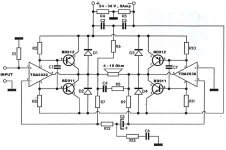
For a subwoofer amp, a bought this kit which uses two TDA2030 and 4 transistors. It also worked ok, but after some time Tda chips would die and rarely transistors also. I replaced them few times but it's clear that there something wrong.
This amplifier is claimed to give 200w in 4Ohm load, it needs 24-36v for supply and 5 Amps. I have specially made toroidal transformer which has 12 v out for 5 channels and 23V, 5 Amp for this amp. 10.000uF capacitor is after diodes and after that there's switch who's connected to amp module.
With this amp i had startup problems. After I turn on main voltage to transformer, i have second switch after supply capacitor. Amplifier will go small "bum" after switching, and 2 seconds later it would shoutly do another "BAM, BAM".") D nice description). I assume that this is the reason why this amp won't last long and that i need some kind of soft start circuit.
D nice description). I assume that this is the reason why this amp won't last long and that i need some kind of soft start circuit.
If this is a problem, then please show me the simplest automatic soft start cicuit. This amp has beautiful sound and it has tons of power which i need for sealed subwoofer (with linkwitz transform)which i'am going to build.
Also if you could explain me how effective is that voltage divider at the top of schematics, it looks too simple for that amount of power.
Thanks a lot!
Few years ago i decided to make 5.1 system for a pc. I made speakers and amplifier which has 5 channels with TDA2005 (bridge mode) and they work great (20w each) + subwoofer amp.
For a subwoofer amp, a bought this kit which uses two TDA2030 and 4 transistors. It also worked ok, but after some time Tda chips would die and rarely transistors also. I replaced them few times but it's clear that there something wrong.
This amplifier is claimed to give 200w in 4Ohm load, it needs 24-36v for supply and 5 Amps. I have specially made toroidal transformer which has 12 v out for 5 channels and 23V, 5 Amp for this amp. 10.000uF capacitor is after diodes and after that there's switch who's connected to amp module.
With this amp i had startup problems. After I turn on main voltage to transformer, i have second switch after supply capacitor. Amplifier will go small "bum" after switching, and 2 seconds later it would shoutly do another "BAM, BAM".
D nice description). I assume that this is the reason why this amp won't last long and that i need some kind of soft start circuit. If this is a problem, then please show me the simplest automatic soft start cicuit. This amp has beautiful sound and it has tons of power which i need for sealed subwoofer (with linkwitz transform)which i'am going to build.
Also if you could explain me how effective is that voltage divider at the top of schematics, it looks too simple for that amount of power.
Thanks a lot!
Attachments
Thanks Myanmar for posting.
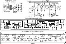
Yours schematics looks almost identical. All values are the same, only transistors are different.
Also i have 23V transformer output which passes trough one capacitor (10.000uF) and then goes to voltage divider on board, while your schematic has voltage divider made from two 10.000 uF capacitors. Does that make any difference?
If you, or anyone else has some ideas, please write.
If you need values of elements i'll write them.
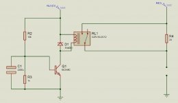
Ok, i have constructed this schematics for soft start. Main resistors are connected after rectifier and capacitor, not before primary transformer winding as elliot sound projects suggests. It will run power trough resistors for about 2-4 seconds (i'll test what's best) and then it will bypass resistors. I just need to chose the best value for main resistors. Voltage for this (12v) will be provided by secondary 12 winding. Schematics is on the picture.
Any suggestions?
Any suggestions?
Attachments
I will post the results, only problem is that i will begin with rebuild in one month, because i also have no time now.
As the amp itself it really sounds decent, don't hesitate with project. It has plenty of power and it doesn't dissipate to much of it. Also it's pretty cheap.
I also have to build subwoofer for it , and 5.1 volume control for the whole amp, so i'm now in phase where i am calculating and drawing, and in one month i will build it.
And about that soft start i drawn, i think that 4x10Ohm (9 watts, ceramic) resistors in series will be good for limiting current. With 40 Ohm at 33 volts, max dissipation would be 27 watts (9x4W is max for resistors). Also in series with them i will put melting fuse used in transformers (10Amps, 120C) just to be sure if for some reason relay doesn't switch and resistors stay on longer than expected.
Yes, that is base resistors.
I placed with 2SA1302 & 2SC 3281 instead of BD....
My amp no need soft start.
Becaus I didn't heard any sound when I switch on. ( may be very small sound ).
I think
1. small amount of capacitors ( 4700uf )
2. may be cancle each other in bridge mode.
Is that true ?
Pls, explain.
Bye.
I placed with 2SA1302 & 2SC 3281 instead of BD....
My amp no need soft start.
Becaus I didn't heard any sound when I switch on. ( may be very small sound ).
I think
1. small amount of capacitors ( 4700uf )
2. may be cancle each other in bridge mode.
Is that true ?
Pls, explain.
Bye.
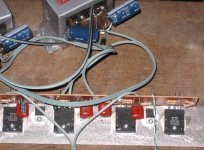
From picture i can see that you use small transormers and they are not toroidal, and because of that you don't have problems with starting up the amp, which is great news for you, but that transformers should be about 60w (12V 5A) (are they?).
As for transistors, that resistors as i see it, should just put input voltage for transistors at optimal level, i think it's not a big difference between 2 and 2,2ohm . Also it depends on different transistors. But I would like, if somebody who knows that answers you.
If amp is working properly than everything should be fine. What do you think about sound of the amp, and are you satisfied with it?
Best Regards,
Mx
Yes, it's a good point, but i'm driving a 8Ohm speaker , at 100w. Also i know that this schematic isn't the best (far from that) but i have it for a long time, and my transformer is made for it. If you know some discrete schematics for similar amp at 33v, please post.
I'm sorry Myanmar that you're not satisfied with sound, my amp sounds pretty good, and it puts some serios db-s from speakers. Maybe there's a problem with that transistors you changed.
I tested the amp many times with 3 way speakers, but in my case,only use for this amp is driving a 8 ohm subwoofer for pc speakers system up to 100 Hz. That's why i don't need higher quality amp, although i would like it to be more reliable.
- Status
- This old topic is closed. If you want to reopen this topic, contact a moderator using the "Report Post" button.
- Home
- Amplifiers
- Chip Amps
- 200w Tda2030 Amp - Need Help !