Hi there guys,
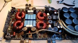
I'm working on a SPL Dynamics D8s (same amp as the DD M4a and those kinds).
There were some defect output fets and a defect IRS chip.
I changed all 4 IRS21844s to IX21844n chips.
Changed the high speed diodes on the driver board, changed the 2D transistors. Fixed the 15v power supply. I measured a clean looking PWM square wave about 2Khz on all 4 low side output banks (high side does not produce a square wave without output fets installed).
I plugged in one fet per bank, instantly exploding and banging out some output fets on 8.5v PS voltage (120V+ rail voltage). Scary stuff.....
I watched a video where this problem occured with FAN chips causing all banks to shortly bump a DC voltage on the output fets gate. This DC bump on the gate does not occure in this amplifier. I can't measure any DC bumps on the gate.
Does anybody experienced the same problem or know what is causing this?
Is the rail voltage building fully before the output is enabled? See attached for example.
http://www.bcae1.com/temp/ampstartup01.mkv
http://www.bcae1.com/temp/ampstartup01.mkv
The amp is building up close to it's maximum rail voltage before banging out the fets for so far I can remember.
Without output fets installed there is no issue and the amp is pulling +-2.5a idle on 8.5v PS.
The amp is doing the same rail voltage buildup, but i quess when it builds a PWM it blows.
Without output fets installed there is no issue and the amp is pulling +-2.5a idle on 8.5v PS.
The amp is doing the same rail voltage buildup, but i quess when it builds a PWM it blows.
have you checked all GATE and PULLDOWN resistors?
Even if seems to be ok, when a first catastrphic failure occur, the gate resistors togheter with the four 2watts VS resistors are the first stuff that you must regardlessly replace because they are the primary path that the released incredible amount of power go across, damaging the GATE RESISTORS and damaging or destroing the VS resistors.
So if you check this resistors and you find a (apparently) good values, this not mean that is necessarly ok, because, if you measure it with no power, you will read a apparently good value, but when you turn on the amp, this value can vary, causing the second premature catastrophic failure.
Perry, I currently only have a single channel power supply of 0-30v.
Thanks for your reply Mario.
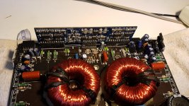
All the Gate and pulldown resistors read OK. Nothing seems slightly burned and reads nice in tolerance.
The four green coloured 2w resistors read about 5ohm each. Those are the feedfack resistors correct? They are placed close to the driver board correct?
I measured again on all 4 banks low side gate drive. The duty cycle is 40% at the 2Khz wave.
Would this give a clue to the problem? Or would the high side compensate this with a 60% duty cycle.
Thanks for your reply Mario.
All the Gate and pulldown resistors read OK. Nothing seems slightly burned and reads nice in tolerance.
The four green coloured 2w resistors read about 5ohm each. Those are the feedfack resistors correct? They are placed close to the driver board correct?
I measured again on all 4 banks low side gate drive. The duty cycle is 40% at the 2Khz wave.
Would this give a clue to the problem? Or would the high side compensate this with a 60% duty cycle.
Last edited:
When amps are destroying the outputs and driver ICs, using a low-voltage supply to supply rail voltage is sometimes useful to find the problem. The basic idea is on the following thread. It essentially involves adding a few turns of wire around the transformer then rectifying it and connecting that to the rail caps (original rectifiers removed).
https://www.diyaudio.com/forums/car-audio/319174-4000-1-a-7.html#post5492949
https://www.diyaudio.com/forums/car-audio/319174-4000-1-a-7.html#post5492949
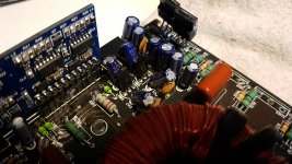
So, fixed the + and - rail voltage of 15v.
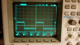
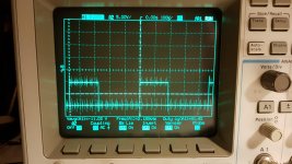
Probed the low side gate drive (ch1) and - rail voltage (ch2).
Photo 1 is the low side gate drive, only ch1
Photo 2 is the low side gate drive both channels on screen.
The noise is unfortunately because of the 10x of the probes. Setting the probe on 1x makes the noise to dissapear. So try to ignore the noise.
Fets are all out. Tried a 20Hz RCA tone, low-side gate drive seems to create a correct variable pwm switching.
Attachments
Last edited:
You can install the FETs. If you want something more indestructible, you can use PS FETs on the output locations since the rail voltage is so low. If you used current limiting like the 12v lamps I suggested, it will be nearly impossible to destroy anything (unless you let something overheat) and you will be able to see if anything shows up as a fault.
What's the frequency of the square wave?
Is the muting circuit holding the oscillation for a short time (normally until full rail voltage is reached)?
Or does oscillation start almost instantaneously?
Is there any DC offset building on the output filter inductors as the amp tries to start?
Are the output FETs heating up after repeatedly shutting down and restarting?
Just powered it on again.
Worked fine??...
Fets don't heat up, no DC bump on the speaker terminal, produces audio with a subwoofer connected.
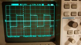
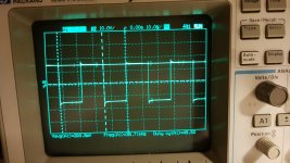
Hard to check for the r-r oscillation start since the amp has almost immediately builded rail voltage. The r-r oscillation starts almost immediately
Photo's is the source pad of the high-side fet and the rail volltage.
Worked fine??...
Fets don't heat up, no DC bump on the speaker terminal, produces audio with a subwoofer connected.
Hard to check for the r-r oscillation start since the amp has almost immediately builded rail voltage. The r-r oscillation starts almost immediately
Photo's is the source pad of the high-side fet and the rail volltage.
Attachments
Perry, I currently only have a single channel power supply of 0-30v.
Thanks for your reply Mario.
All the Gate and pulldown resistors read OK. Nothing seems slightly burned and reads nice in tolerance.
The four green coloured 2w resistors read about 5ohm each. Those are the feedfack resistors correct? They are placed close to the driver board correct?
Yes, you understand of what resistors i'm talking about, but, trust in me, replace it, because you say that you read 5ohm circa, but in your photo i see 2.2ohm resistors.
Is always a good thing replace this inexpensive resistors and save you from another possibly catastrophic premature failure.
Furthermore, what you see on the low side (when the mosfets are not there) can be very misunderstanding, because there is no load (mosfets installed) that waveform will often be present and you will be led to think that everything has gone for the right way, then you install the first mosfets, turn on and see that it works, but when you install all the mosfets (NEW AND EXPENSIVE) then a mess happens.
I always say, it's not worth throwing several hundred dollars and taking risks, rather than being cautious and spending less than $ 1 for 4 new resistors.
Instead, for the issue of switching that starts immediately without waiting for the rail, you may have problems with the muting / delay circuit (KTD1302) or with the circuit of the KTD1304 (MAX transistor) on the driver board.
Perry has given you a schematic of a similar amplifier so you can understand how the 1302 circuit works, but to understand the 1304 you need the driver board schematic.
You are absolutely right about that. I will change all 4 feedback resistors.
Thanks for the diagram Perry. I think I need the driver board diagram.
I checked the driver board as well, looking to some video's of how it should behave, I'm 100% sure this driver board directly starts oscillating.
The KTD1304 reads ok, the problem does not seem to be there.
Are there some specific parts which usually die in this case?
All transistors on the driver board read OK. As well as all diodes.
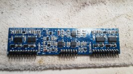
Is there anyone who has a diagram of the driver board?
IX21844n pin1 is directly recieving a 37khz square wave.
Do you know or this is correct? Or should this be delayed.
Thanks for the diagram Perry. I think I need the driver board diagram.
I checked the driver board as well, looking to some video's of how it should behave, I'm 100% sure this driver board directly starts oscillating.
The KTD1304 reads ok, the problem does not seem to be there.
Are there some specific parts which usually die in this case?
All transistors on the driver board read OK. As well as all diodes.
Is there anyone who has a diagram of the driver board?
IX21844n pin1 is directly recieving a 37khz square wave.
Do you know or this is correct? Or should this be delayed.
Attachments
Last edited:
Tried to find the causing, but I can't find a clue.
The problem is 100% on the driver board for sure.
I had the possebility to have a good working driver board for half a day.
With that driver board, it was delayed until full rail voltage and it worked properly.
I compared and measured every single resistor and sot23 package components.
There were a couple resistors out of tolerance and replaced them.
Other than then, both boards measured almost identical, no clues found.
Some things I noticed on the good working driver board:
- IRS21844s Pin1 square wave from 2Khz until full rail voltage is applied. Then it starts oscillating at 36Khz.
Bad driver board
- IX21844n Pin1 square wave from 36Khz directly.
- Pin 2 DC voltage is the same as good working driver board.
Has someone ever fixed this specific problem?
- Home
- General Interest
- Car Audio
- Exploding output fets SPL Dynamics D8s