I'll start off by mentioning this is my first attempt at repairing an amp.
Much of what I've learned has been from Perry's free tutorial and watching some videos by BareVids. I'm not completely versed in all the "lingo" but I have no issue stepping back and doing some research to understand better.
The amp in question was going into "protect" and immediately shutting down.
I tracked down the issue to a faulty repair by a tech years ago. In which he switched the order of the op-fets/transistor? They placed the IRF640's on both banks at the front and end of the bank. ie: (640,9640...9640,640)
I removed all the op-fets as they were shorted and replaced all the power transistors.
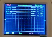
After this I was able to power up the amp without going into protect using both 9V/12V. I then began to check the rail voltage for each back without the op-fets and drivers. I was reading with both a "budget" oscilloscope and a DMM.
With oscilloscope: +53.54V and -47.86V
DMM: +56.5V and -56.5V
On both banks
This is where my issue starts. While checking the voltage on the TL494CN pins I managed to get a reading from pins 6-10 but as I was trying to read pin 5(Oscillator) I could hear a "whining" being emitted from what I believe is the transformer on the power side. I essentially held it on too long and the fuse fault kicked on and the amp powered off. I did try to restart but no luck. I was able to determine a short to ground as when I check for continuity between +12v and GND my DMM "beeped". I also have no continuity between REM and +12v. I did all this with the power driver installed and removed.
I found that if I remove the 2x 40a fuses I would not get a continuity "beep" between +12, REM, and GND. Now I'm not too sure how to proceed in finding this short. Any help would be greatly appreciated.
IC# TL494CN
Pin 1: N/A
Pin 2: N/A
Pin 3: N/A
Pin 4: N/A
Pin 5: N/A
Pin 6: 3.62v
Pin 7: 0v
Pin 8: 11.71v
Pin 9: 4.48v
Pin 10: 4.48v
Pin 11: N/A
Pin 12: N/A
Pin 13: N/A
Pin 14: N/A
Pin 15: N/A
Pin 16: N/A
My tools:
Budget Solder Iron and Solder Sucker
Aukuyee Q15001 Digital Oscilloscope
UEI DM383B DMM
Much of what I've learned has been from Perry's free tutorial and watching some videos by BareVids. I'm not completely versed in all the "lingo" but I have no issue stepping back and doing some research to understand better.
The amp in question was going into "protect" and immediately shutting down.
I tracked down the issue to a faulty repair by a tech years ago. In which he switched the order of the op-fets/transistor? They placed the IRF640's on both banks at the front and end of the bank. ie: (640,9640...9640,640)
I removed all the op-fets as they were shorted and replaced all the power transistors.
After this I was able to power up the amp without going into protect using both 9V/12V. I then began to check the rail voltage for each back without the op-fets and drivers. I was reading with both a "budget" oscilloscope and a DMM.
With oscilloscope: +53.54V and -47.86V
DMM: +56.5V and -56.5V
On both banks
This is where my issue starts. While checking the voltage on the TL494CN pins I managed to get a reading from pins 6-10 but as I was trying to read pin 5(Oscillator) I could hear a "whining" being emitted from what I believe is the transformer on the power side. I essentially held it on too long and the fuse fault kicked on and the amp powered off. I did try to restart but no luck. I was able to determine a short to ground as when I check for continuity between +12v and GND my DMM "beeped". I also have no continuity between REM and +12v. I did all this with the power driver installed and removed.
I found that if I remove the 2x 40a fuses I would not get a continuity "beep" between +12, REM, and GND. Now I'm not too sure how to proceed in finding this short. Any help would be greatly appreciated.
IC# TL494CN
Pin 1: N/A
Pin 2: N/A
Pin 3: N/A
Pin 4: N/A
Pin 5: N/A
Pin 6: 3.62v
Pin 7: 0v
Pin 8: 11.71v
Pin 9: 4.48v
Pin 10: 4.48v
Pin 11: N/A
Pin 12: N/A
Pin 13: N/A
Pin 14: N/A
Pin 15: N/A
Pin 16: N/A
My tools:
Budget Solder Iron and Solder Sucker
Aukuyee Q15001 Digital Oscilloscope
UEI DM383B DMM
Last edited:
Refer to the power supply FETs as PS FETs. All large transistors are power transistors.
Why n/a on the 494?
When you refer to beep, do you mean a steady tone for as long as you have the probes on or a short beep?
Did you blow the PS FETs when probing pin 5?
Post a working link to the owner's manual for the meter you have.
Why n/a on the 494?
When you refer to beep, do you mean a steady tone for as long as you have the probes on or a short beep?
Did you blow the PS FETs when probing pin 5?
Post a working link to the owner's manual for the meter you have.
Refer to the power supply FETs as PS FETs. All large transistors are power transistors. Will do.
Why n/a on the 494?
I didn't start measuring in sequential order from 1-16. I was only able to get the measurements I posted.
When you refer to beep, do you mean a steady tone for as long as you have the probes on or a short beep?
Sorry. It's a steady tone.
Did you blow the PS FETs when probing pin 5?
Just got home from work and I did blow one PS fet. I just removed it and no longer have a short to ground.
But I have no continuity between +12 and REM.
Post a working link to the owner's manual for the meter you have.
https://www.ueitest.com/ecommerce/site/content/PDFs/DM383/DM383%20MANUAL%20English.pdf
What do you mean by:
But I have no continuity between +12 and REM.
Honestly I should have asked if I needed continuity between the two. But now thinking about it maybe that should not have continuity. Is this correct?
What are you expecting to read between the B+ and remote?
I hope my comment above answers this.
What about if you reverse the probes?
With continuity mode. I get "OL"
I checked in Diode-mode and can see a charge being applied between B+ and REM.
I'm assuming since I no longer have any shorts or open circuits that it's safe to power it up?
I have an adjustable AC-DC that I can use 9V or 12V at 2A
Don't use continuity mode. Use either ohms or diode-check.
Ok. Is there a reason why I shouldn't use continuity mode? (Not questioning your advice.)
Most amps will have problems at 9v. Is the 12v@2A all that you have for a 12v supply?
I have an ATX PSU that is 12v@32A max.
I did try the 9V@2A yesterday and the amp powered up and the relay clicked on but the protect light stays on.
I did not wait a long time to see if the protect light would go off.
Should I use the ATX PSU to power the amp @12v? I'm assuming it's not too safe as I have no control over the current. But for now that's all I have. Or stick with the Ac-Dc?
Any thoughts or ideas on why pin 5-6(TL494)would cause a whine and go into protect mode?
As mentioned earlier I believe the whine is emitted from the transformer behind the ps driver. Could it have a possible short in the winding?
I can supply pics if needed.
Any thoughts or ideas on why pin 5-6(TL494)would cause a whine and go into protect mode?
As mentioned earlier I believe the whine is emitted from the transformer behind the ps driver. Could it have a possible short in the winding?
I can supply pics if needed.
The 2A may work.
The ATX can be used with a low-rated fuse or with a resistor in the B+ line.
Will the low-rated fuse be for use on the amp board?
Would two 10A fuses be sufficient enough for testing with the ATX? Should I go lower(2x 5A)?
The meter was likely affecting the frequency. I don't know why it went into protect. Shorting an FET should have shut the 2A PS down.
The 2A PS might have gone into over-protection but I did not notice. I'll keep an eye on the power light.
This is the PS.
https://www.amazon.com/SoulBay-Universal-Switching-Selectable-Electronics/dp/B01N7RS0NG/ref=sr_1_10?dchild=1&keywords=AC-DC+12v+2A+adjustable&qid=1634224104&sr=8-10
Did you have it in DC volts mode?
I do have it in DCV. Below is a link to a pic showing the connection points I'm using on the DMM.

Not all amps have onboard fuses but it it does, you can install the fuse in the amp.
Most amps with multiple fuse holders have the fuses in parallel so you can install a single fuse.
Bear in mind that having a fuse or limiter doesn't give complete protection. You have to be very observant. The FETs in the PS can overheat and fail even with limiters.
If you use a limiter (2 ohm 100w tubular/cylindrical wirewound resistor) and connect a 12v piezo buzzer across it, it will give an audible indication of the current through the resistor.
https://www.mouser.com/productdetail/ohmite/l100j2r0e?qs=06/EEXcdZWQyq%2bVjS1rN4g==
I really appreciate your help and insight.
As I'm waiting on a new round of transistors to arrive.
I wanted to pick you brain regarding the PS driver. Specifically the TL494.
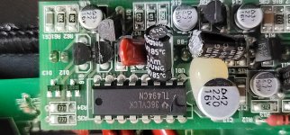
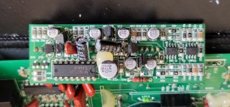
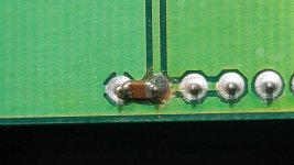
When I first started working on the driver I noticed a small brown smd resistor between pins 15-16. With my lack of knowledge in this field I figured this was not suppose to be there. In retrospect maybe I shouldn't have. Now I'm wondering if this is the cause of my issue with pins 5-6. I have one photo of the resistor between 15-16 and two photos of the driver board.
Memphis Amp Pics - Google Drive
As I'm waiting on a new round of transistors to arrive.
I wanted to pick you brain regarding the PS driver. Specifically the TL494.
When I first started working on the driver I noticed a small brown smd resistor between pins 15-16. With my lack of knowledge in this field I figured this was not suppose to be there. In retrospect maybe I shouldn't have. Now I'm wondering if this is the cause of my issue with pins 5-6. I have one photo of the resistor between 15-16 and two photos of the driver board.
Memphis Amp Pics - Google Drive
Did you buy from a reputable distributor?
I don't think that could cause the problem you had when probing pin 5 but I can't say that definitively. It's acting as a filter for the on-board 5v regulator. If you want to add a cap and don't know the value, a 0.1uF would be a suitable cap.
I looked at some of the images I have of these driver boards and none had that cap.
In the future, please post all images to the forum so that they will not be lost.
To upload photos click the following:
Go Advanced
Manage Attachments
Browse
Upload
Repeat as necessary
Preview post to see how the post will look.
Click Submit Reply to send it to the forum.
Did you buy from a reputable distributor?
Unfortunately I did not find any in stock on Mouser and Digi. As these are obsolete
I ordered them all off Amazon.
I tried searching for an alternative with the same exact specs. But no luck.
The ones I found have slightly different specs. Could you verify the ones I found as alternatives? If these are not suitable could you recommend some?
IRF9640=IRF9640PBF(No Stock) / 2nd Alt=IRF9240PBF
IRF3205=IRF3205ZPBF (No Stock) / 2nd Alt= PHP191NQ06LT,127
IRF640=IRFB4020PBF
I did find on here you verified replacements for the rectifiers.
YG225N2=MUR1620CT
YG225C2=MUR1620CTR
I don't think that could cause the problem you had when probing pin 5 but I can't say that definitively. It's acting as a filter for the on-board 5v regulator. If you want to add a cap and don't know the value, a 0.1uF would be a suitable cap.
I looked at some of the images I have of these driver boards and none had that cap.
Essentially I did the same. I reviewed all the available photos on here and online. I could not find any which had that resistor between pin 15-16. Hence why I removed it.
Any thoughts on why someone would place a resist on that +/- 2in error amp?
In the future, please post all images to the forum so that they will not be lost.
Will do.
To upload photos click the following:
Go Advanced
Manage Attachments
Browse
Upload
Repeat as necessary
Preview post to see how the post will look.
Click Submit Reply to send it to the forum.
This morning I did try to scope pin 6-5(TL494) with my handheld scope and I could still hear the "whine" which I believe is coming from the transformer. I was hoping to get a Voltage readout or see a waveform on the pins. But I did not leave it on for long as the PS fets were getting really hot and I did not want to "short" anymore of them. Currently I only have four installed on Q21-24. The others were shorted because of the pin 5 issue.
Can I install two PS fets on both ends of the bank to power up and test? Or would I need four PS fets on both ends? Or do I need to install them all?
I did have all of them installed and the amp seemed to run fine for a substantial amount of time with no load and the PS transistors removed. With no overheating or protect issues.
Or should I just move onto installing the PS transistors after the fets are installed?
When checking the op-gate without the PS transistors installed for voltage should I see a waveform too? Last time I checked with the scope only a line noting the Voltage can be seen on the scope. I can post pics if you'd like.
Attachments
Last edited:
Did you (properly) check the original output FETs? They could not have all been shorted.
With amazon or ebay, you have a real chance of getting counterfeit parts.
The error amp isn't being used as an error amp. Pin 16 is grounded. The cap is between the 5v regulator output and ground. The cap being there isn't a problem.
I was referring to the capacitor acting as a filter on the 5v regulator, not pin 5.
Why are you so intent on metering/viewing the signal on pin 5?
Why did you want to replace the rectifiers?
Before installing any any FETs, I'd suggest loading the FET locations with a 0.1-0.01uF cap (G-S).
Did you (properly) check the original output FETs? They could not have all been shorted.
Since I don't have an ESR I cannot verify them. I checked based on the info on your site using a DMM. Based on these test I determined a few of them were bad.
This is the reason why I replaced all. Also since the amp was serviced before some of the op-transistors were not from the same manufacturing batch.
With amazon or ebay, you have a real chance of getting counterfeit parts.
I completely understand.
The error amp isn't being used as an error amp. Pin 16 is grounded. The cap is between the 5v regulator output and ground. The cap being there isn't a problem.
I was referring to the capacitor acting as a filter on the 5v regulator, not pin 5.
Why are you so intent on metering/viewing the signal on pin 5?
Honestly the only reason was because it caused the short to ground issue.
I was merely trying to read the voltage on the TL494 and fell down the rabbit hole.
I'll leave it alone.
Why did you want to replace the rectifiers?
I don't want to replace them. Only asking for future reference and for a better understanding on finding alt replacements for these types of electronic components.
Before installing any any FETs, I'd suggest loading the FET locations with a 0.1-0.01uF cap (G-S).
Are these suitable? https://www.amazon.com/0-01uf-0-001uf-Polyester-Capacitor-Assortment/dp/B07D1J5LSD
Would I be placing them into Gate and Source?
Could you explain your suggestion and what's the purpose for it?
I figure one or maybe the only reason is to avoid burning out more fets.
Amazon again. You're going to drive me to drinking. Mouser and Digikey are very user friendly. Any mylar/film capacitor will work.
You don't need an ESR meter. All you need is a DMM and you can virtually 100% of the time whether they're good or bad.
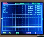
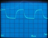
The capacitor is to load the drive circuit to determine if the drivers are working as they should. You look at the waveform on the gate. It should look much like the image below. Doing this BEFORE installing the FETs will save a lot of time.
You don't need an ESR meter. All you need is a DMM and you can virtually 100% of the time whether they're good or bad.
The capacitor is to load the drive circuit to determine if the drivers are working as they should. You look at the waveform on the gate. It should look much like the image below. Doing this BEFORE installing the FETs will save a lot of time.
Attachments
Big brother Amazon
If and when I need to order from a legit source I'll use Mouser or DigiKey.
Especially now that I finally noticed they have a substitute tab.
For now I'll order the 0.1uf caps.
In the meantime for clarity sake.
Are these caps to be installed in the PS fets locations on Q17-Q24?
Would I be checking the gates on the fets/caps or gate for the op-transistor after the cap install?
This is for the PS FET locations.
If ALL gate resistors are within tolerance, you can check only one FET location in each bank.
You check on the gate pad for the FET where the capacitor is installed.
Set your scope to the same settings shown in the image above and post the waveform images.
If ALL gate resistors are within tolerance, you can check only one FET location in each bank.
You check on the gate pad for the FET where the capacitor is installed.
Set your scope to the same settings shown in the image above and post the waveform images.
- Home
- General Interest
- Car Audio
- Memphis 16-MC1000D Ground Short (Newbie 1st Post)