Hello Guys,
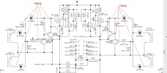
Please help me trace or eliminate the ringing signal from the high side output side of the T2000 and T2001. I believe this is the root cause of ringing on positve side of output fets but please correct me if I am wrong. This is the first time I trouble shoot this kind of amp.
44H11 and 45H11 readings are good I also re soldered it. I also pulled out driver transistors and all tested fine no leak.
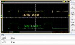
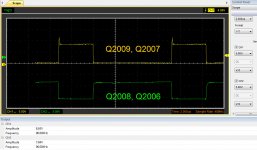
Attached are the signal forms.
Please help me trace or eliminate the ringing signal from the high side output side of the T2000 and T2001. I believe this is the root cause of ringing on positve side of output fets but please correct me if I am wrong. This is the first time I trouble shoot this kind of amp.
44H11 and 45H11 readings are good I also re soldered it. I also pulled out driver transistors and all tested fine no leak.
Attached are the signal forms.
Attachments
Hello Perry,
It is a USB scope Hantek 6022BE
http://www.hantek.com/products/detail/31
I already tried swapping it with channel 2 (green) and it really reads the same.
I am also repairing a Rockford T2500bd right now and it doesn't have that ringing as shown by the Rockford T1000bd after I successfully brought it back alive by replacing the two 5110 ICs. It just has another issue though with power supply section but will post another thread if I can't fix it after.
For digital scopes it's generally a math function (ch1 minus ch2). Many times, ringing can be due to a bad reference. The following is the basic differential setup.
A differential input uses two inputs to produce a single waveform. The simplest way to get a differential input is to use a differential probe. A differential probe has two signal leads and a mixer amplifier built into it. It feeds the scope a normal signal (a composite of the two signals input into the differential probe). The problem with differential probes is that they're expensive.
The alternative is to use two scope probes and and both inputs of your oscilloscope. This is how you have to set up your scope:
Two probes
Both scope inputs used
Input set to add
Both channels set to DC coupling
Both vertical amps set to the same voltage
Ch2 input set to invert
Bandwidth limited (works best for most measurements in car amps)
Trace aligned to the reference line on the scope's display
Ground leads for both probes connected together (not always necessary)
After setting up the scope, you need to confirm that it's working as it should. With the vertical amp set to 5v/div, touching the probe that's connected to Ch1 to the positive terminal of your 12v power supply should make the trace deflect about 2.5 divisions up from the reference (like it always does, seen below). Doing the same with the probe connected to Ch2 should make the trace deflect down about 2.5 divisions. Touching both probes to the positive terminal of the 12v power supply should cause no deflection. If it does, something isn't right.
I know that this may not be as simple as the isolated scope but if you take the time to learn it one time (even if it takes an hour or more of your time), you have that knowledge and this tool to use for the rest of the time you need to use a scope. Using the analog scope will give you much larger and cleaner waveforms.
Hello Perry,
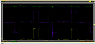
I am now back checking this AMP. I got the differential mode setup going. A purple line appeared in the middle. I set the ch2 inverted. If I touch both probes with my fingers, the purple line is not moving. I guess that is how differential mode should work right?
How can I use this in checking this amp?
I actually tried using both probes left the ground floating in the air and I don't understand it. There is still ringing in the purple line. The photo is taken directly to the transformer without the 12 diodes and 6 driver transistors because I pulled it out
Attachments
Please use circuit board designations. Which transformer?
The circuit needs to be complete to determine if the waveforms are normal.
When in differential mode. if you place both probes on the same point, the trace should not move. It should remain a straight line. It's essentially like a multimeter, when you place both probes on one point.
The circuit needs to be complete to determine if the waveforms are normal.
When in differential mode. if you place both probes on the same point, the trace should not move. It should remain a straight line. It's essentially like a multimeter, when you place both probes on one point.
Hello Perry,
Sorry the transformer I tested are the T2000 and T2001. The ones being driven by the 5110 ICs. the primary looks good.
It means I got this differential mode right then") It is convenient because I don't have to force contact the ground clip I can just leave it hanging. I am just having a bit difficulty on the trigger though
It is convenient because I don't have to force contact the ground clip I can just leave it hanging. I am just having a bit difficulty on the trigger though
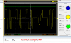
The problem with this this unit is that it gives out high frequency audio like around 10Khz without audio input, and FETS are heating quickly (clamped on heatsink), then class D signal before the output filter is not normal. The output filter tested fine when I pulled it out. As well as the output caps.
I will put these all together and get another reading.
Sorry the transformer I tested are the T2000 and T2001. The ones being driven by the 5110 ICs. the primary looks good.
It means I got this differential mode right then
It is convenient because I don't have to force contact the ground clip I can just leave it hanging. I am just having a bit difficulty on the trigger though The problem with this this unit is that it gives out high frequency audio like around 10Khz without audio input, and FETS are heating quickly (clamped on heatsink), then class D signal before the output filter is not normal. The output filter tested fine when I pulled it out. As well as the output caps.
I will put these all together and get another reading.
Hello Perry,
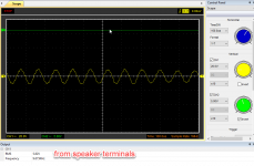
Yes it is audible in the speaker. I have also tested it with a 2 ohm subwoofer the first time this came in. It was not that audible because it was a sub but it is really there. This is very audible in the subwoofer inside the car where this was installed.
I also tested it with a 4 ohm full range speaker the other day when I sent the screenshot. It is very audible
Last edited:
Was it a constant tone or did it vary in frequency similar to the file below?
http://www.bcae1.com/temp/cooleditmixedoscillator01.wav
On the output driver board, there is an IC near the corner. Near that IC, you'll find C35. What's the frequency on the top end of that capacitor?
What's the frequency on the power supply FET gates?
http://www.bcae1.com/temp/cooleditmixedoscillator01.wav
On the output driver board, there is an IC near the corner. Near that IC, you'll find C35. What's the frequency on the top end of that capacitor?
What's the frequency on the power supply FET gates?
Hello Perry,
It is a constant tone. I can't find C35 in the output card.The capacitors in output card start with C2xx. What IC is it connected to?
In the diagram, I can only find C235 connected to u208 lm 6172 but it is "not used" and not present nor indicated in the actual output card
the PS fet frequency is 24.1Khz to 24.39Khz on both banks
Last edited:
- Home
- General Interest
- Car Audio
- Rockford T1500-1bd ringing outuput