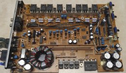
I have this amp I would like to fix. It was my very first amp. It won't stay on. The power LED pulses on and off, then flickers very quick, then repeats the cycle. I am hearing some clicking or popping on the board but can't really identify where and it's not totally consistent when it will do it with regards to the LED cycling.
The board doesn't look bad to me. Nothing seems burned. No shorts in the 4 IRFIZ44Gs (https://www.vishay.com/docs/91189/91189.pdf).
I have nothing connected to the inputs or speaker connections. The voltage on the RCA shields jumps up to 9.5-9.6v then starts dropping and gets to 2.x-4.x then goes back up during the cycle. There is no connection to any of the speaker terminals and the RCA shields. This seems wrong to me but I don't know where to go from here.
Found the manual and it has schematics in it, but they aren't super readable.
I'd appreciate any help or ideas on what to look at to try and figure out where the problem is. Thanks. I have a scope and transistor tester as well as an auto-ranging dmm.
I can get better, zoomed in pictures of any areas, if needed. These had to be resized smaller to fit the attachment requirements. Nothing has been done to this amp since I have owned it and I believe it was new, so something has failed.
Attachments
Last edited:
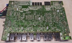
Output transistors - I checked all 3 legs on the B1587s, D2438s, D2343s and nothing was shorted.
Transformer - I tried to figure out if the transformer was shorted since that is what your guide suggested and I thought I had figured it out but it didn't seem to be shorted. I thought it would be more obvious but am not sure of the right way to check it and I couldn't find a guide telling me how to test it. What I did was check the primary windings and secondary windings and they weren't shorted to each other (I could be wrong but I assumed these separate areas of 4 connections are the primary and secondary windings). All 4 blue are connected to each other and all 4 green are connected to each other (see transformer.jpg). All 4 green are also connected to the ground terminal.
I had even looked up the part (CTT1035) thinking that was the problem but couldn't get any stats on it for a replacement. After this I compared it to another amp I have and its non-bridge outputs were connected to the rca shields as expected so I made this post looking for help.
B+ & RCA resistance - it just kept climbing and seems to be charging up. I stopped when it got to over 110k. Seems like it could keep going as long as my meter has battery.
Thanks for the response!
Attachments
Last edited:
If you ground the RCA shields with a small jumper wire, does thew amp still cycle?
Note: The left RCA and right RCA shields are not connected to each other. The two lefts are connected to each other. The two rights are connected to each other.
I ran a wire from ground to one of the left shields and one of the right shields and turned it on, no difference was observed.
If you are still stumped, some of the common issues with this era of Pioneer amplifiers are bad solder joints at various places. The most often areas I have seen are around the heat sink mounted devices like the outputs and sometimes the emitter resistors. I have also seen poor solder joints on the RCA jacks. Look around the board as you may find other areas.
Another area that I have seen need attention is the +/- 15V regulator area. That area of the board is usually discolored from the heat, and those solder joints are are well baked. Check the zener diodes there as well.
Another area that I have seen need attention is the +/- 15V regulator area. That area of the board is usually discolored from the heat, and those solder joints are are well baked. Check the zener diodes there as well.
Leave the RCA shields grounded. There should no longer be any DC on the shields.
Is pin 12 of the TL494 pulsing between 0 and 12v?
Did you check the output transistors to see if any are shorted?
Correct. There is no DC on the shields when I keep them grounded.
The scope shows a pulse jumping up to 12.2v on pin 12 vcc of the NEC uPC949C chip. It appears to move in sync with the power LED.
I checked all of them for shorts. It was the first thing I did since it seems easy and I was hoping it would be the issue as I could easily buy new ones and replace them.
When I tried to measure the ohms of all the 6 configurations according to your guide, sometimes it would just keep moving the ohms for as long as I would hold it on there. I don't understand if that's good or bad. I realize the circuit can take a charge from the meter but on those readings I wouldn't know what to report or how long to wait.
Do I need to desolder all the output transistors and test them in my little esr/transistor tester device, would that be helpful?
Thanks.
Last edited:
I'd recommend using a standard multimeter for testing.
You should not read anything near 0 ohms between any of the legs of any individual transistor.
You stated that you checked the Z44s. Did you also check the output transistors?
I don't have a great meter. I was just using my Klein Tools CL110 and then tried it with my Mastech MS8268. Anyway, I kind of just started taking the reading when it jumped up and then stopped getting larger beyond the decimal and it seems like that was accurate enough. I had done all the readings of all the 6 configurations from here (transistortestpage01) with the diode check and there were no shorts.
I did all the ohms readings for all the output transistors and they were pretty consistent except for Q332 standing out with 4 readings that didn't match up with the others. I had wrongly thought that checking for shorts was enough, if this is the issue.
For the six configurations measurements 1, 3, 5 and 6 stand out as different.
Code:
Test Lead Config.       | Q332       | Q328, Q330, Q326, Q329 Q325, Q331, Q337
1                       | OL         | ~38.x k ohm
2                       | 25.x k ohm | ~25.x k ohm
3                       | 9.95 M ohm | ~38.x k ohm
4                       | 25.6 k ohm | ~25.x k ohm
5                       | 9.98 M ohm | ~13.x k ohm
6                       | OL         | ~12.x k ohm
Last edited:
Check the value of the 4 0.22 ohm resistors in that channel.
It's good to see someone still using Flash.
My meters say .2 ohms for them; seem like they are within tolerance.
Flash is a great tool. Like many inventions it seems to have been misused by some and those security issues had a good bit to do with it being taken out of browsers by default.
For clarification, the readings that you need to compare are for other transistors with the same part number.
Remove and check Q332 out of the board. Also remove another of the 2SB1587s to compare its readings if you're unsure of the readings. Some multimeters have trouble checking darlington transistors.
Remove and check Q332 out of the board. Also remove another of the 2SB1587s to compare its readings if you're unsure of the readings. Some multimeters have trouble checking darlington transistors.
For clarification, the readings that you need to compare are for other transistors with the same part number.
Remove and check Q332 out of the board. Also remove another of the 2SB1587s to compare its readings if you're unsure of the readings. Some multimeters have trouble checking darlington transistors.
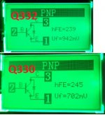
Q332 reads as basically the same out of the board as Q330, which I also pulled. The only weird thing of note that was different was measurement 6, Ohms reading on Q332, it did count up resistance at first and then it was counting down then read OL. I couldn't get it to read resistance after that, so that was a bit weird.
Code:
Test Lead Config.       | Q332 Ohms | Q332 Diode | Q330 Ohms | Q330 Diode
1                       | OL        | OL         | OL        | OL
2                       | OL        | OL         | OL        | OL
3                       | 17.74 M   | 0.576 v    | 17.54 M   | 0.576 v
4                       | 18.47 M   | 0.597 v    | 18.40 M   | 0.596 v
5                       | 10.00 M   | 0.482 v    | 9.92  M   | 0.482 v
6                       | OL        | OL         | OL        | OL
I also connected them to my little transistor tester and attached that pic. They read a bit differently in there.
Attachments
For the locations where you removed those transistors, measure the board the same way that you did when the transistors were in the board. Does the location for Q332 read different from Q330?
Yes, it does. The 1st and 5th test lead configurations stand out for the differences in the Ohms readings.
Code:
Test Lead Config.       | Q332 Ohms | Q332 Diode | Q330 Ohms | Q330 Diode
1                       | 13 k ++   | 0.646 v    | OL        | 0.572 v
2                       | 25.7 k    | OL         | 25.6 k    | OL
3                       | 13 k ++   | OL         | 15 k ++   | OL
4                       | 25.7 k    | OL         | 25.6 k    | OL
5                       | 1.7 M     | 0.651 v    | 41.6 k +  | 0.652 v
6                       | 54 k +    | OL         | 40 k +    | OL

+ slowly rising ohms as long as I keep the leads there
++ quickly rising ohms as long as I keep the leads therePull Q312 and Q308 and the corresponding transistors from another channel and compare their readings out of the board.
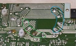
I pulled out Q312, Q308, Q310 & Q306. They tested similarly in my transistor tester. Then I was thinking (and wanted to ask about this), maybe I could remove the voltage regulators to separate the output from the power side and see if the power side behaved differently (I think I saw this in a video)? Anyway, I tried to bend one of the two transistors a bit, to read the board, that I thought did regulation, in the area RiLoWa was saying to focus on, and I noticed Q615 moved too easily. Comparing it to Q614 it was loose. Flipped the board and I could see the traces were broken and would move with it. I desoldered it and put it in my tester. Seems to test fine. Cleaned up the board and soldered it back in. I soldered everything back in and as you probably knew, it still has an issue somewhere else. Those contacts probably made enough of a connection that they weren't the issue.
Last edited:
- Home
- General Interest
- Car Audio
- Pioneer GM-X304