This amplifier got a very weak output power on the speaker terminals.
The output fets are driven 100% fine, the amp pulls a little 2.20a on 14.4v.
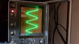
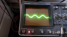
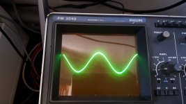
- Photo 1: 50Hz music sine wave on RCA connector. Scope set to 0.2v/div and probe on 1x
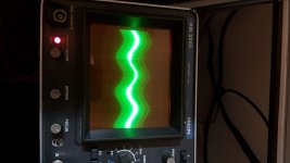
- Photo 2: 50Hz music sine wave on the INPUT pin of the main driver board. Scope set to 0.2/div and probe to 1x. (Seems like a very low amplitude right? Can somebody confirm this?)
- Photo 6: You can see a red dot on one of the vias of the main driver board. This is the vias measured at photo 2.
Did somebody have the same problem as well?
The output fets are driven 100% fine, the amp pulls a little 2.20a on 14.4v.
- Photo 1: 50Hz music sine wave on RCA connector. Scope set to 0.2v/div and probe on 1x
- Photo 2: 50Hz music sine wave on the INPUT pin of the main driver board. Scope set to 0.2/div and probe to 1x. (Seems like a very low amplitude right? Can somebody confirm this?)
- Photo 6: You can see a red dot on one of the vias of the main driver board. This is the vias measured at photo 2.
Did somebody have the same problem as well?
Attachments
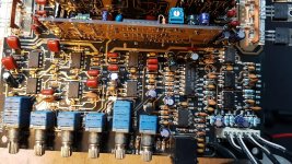
I recieved the schematics from Ground Zero.
I will take some pictures of some waves.
Some extra information. Photo 1 is at the maximum volume of my phone (frequency generator).
Photo 2 is the input of the main driver board, the amplifiers gain is all the way up to the maximum, and all potentiometers are tuned to make sure the maximum amplitude is going to the driver board.
So this is the absolutely maximum I could get.
Attachments
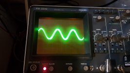
I used my normal phone with this photo's. This phone has a bigger amplitude. (My other phone I use for tests can normally clip every amplifier).
Photo 1: RCA signal 50Hz. 1V/div, probe on 1x
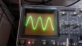
Photo 2: main driver board input. 1V/div, probe on 1x.
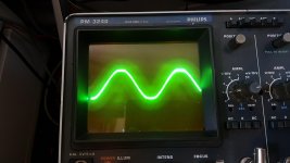
Photo 3: speaker terminal. 1v/Div probe on 10x
Gain on Max
Crossover settings to the highest frequency
Bass boost full at max
Subsonic tuned to the max amplitude
Photo 1: RCA signal 50Hz. 1V/div, probe on 1x
Photo 2: main driver board input. 1V/div, probe on 1x.
Photo 3: speaker terminal. 1v/Div probe on 10x
Gain on Max
Crossover settings to the highest frequency
Bass boost full at max
Subsonic tuned to the max amplitude
Attachments
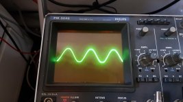
I see... This scope constantly has an offset. It is very temperature sensitive.
I just calibrated again and made some new pictures.
Photo 1: RCA signal 50Hz. 1V/div probe on 1x
Photo 2: Main driver board input. 1V/div probe on 1x
Photo 3: speaker terminal. 1V/div probe on 10x
I set the subsonic to give the maximum output.
Also with 100Hz, no clipping possible.
I just calibrated again and made some new pictures.
Photo 1: RCA signal 50Hz. 1V/div probe on 1x
Photo 2: Main driver board input. 1V/div probe on 1x
Photo 3: speaker terminal. 1V/div probe on 10x
I set the subsonic to give the maximum output.
Also with 100Hz, no clipping possible.
Attachments
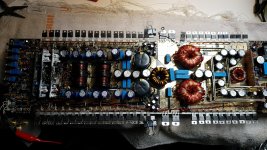
I don't see any amplitude drops in the 22uF capacitors.
Just C101 and C102 has a different amplitude. Maybe that's normal?
C102 has double the amplitude on both terminals as C101. They are both in the beginning at the RCA jack.
Both RCA jacks have the same amplitude.
Just C101 and C102 has a different amplitude. Maybe that's normal?
C102 has double the amplitude on both terminals as C101. They are both in the beginning at the RCA jack.
Both RCA jacks have the same amplitude.
Last edited:
To clarify, you should see the same exact signal level on both terminals of each coupling capacitor. Is that what you have?
Post the AC voltage on every op-amp output in the signal chain from the RCA jacks to the output of the op-amp just before the driver board. For example:
U101-7: ...v AC
U101-1: ...v AC
Do this for all in the chain.
Post the AC voltage on every op-amp output in the signal chain from the RCA jacks to the output of the op-amp just before the driver board. For example:
U101-7: ...v AC
U101-1: ...v AC
Do this for all in the chain.
")
A question, from what reference should I measure? (black probe on?)
I wanted to measure from the GND they use in the filter section (secondary GND?), but it seems like the GND has the 50Hz on it.
I probed U101-1 and GND and it rode 0.003VAC.
The RCA jack probes 0.908VAC referenced to GND.
Is this normal? Or does this already give a clue to example a leaking capacitor?
- Home
- General Interest
- Car Audio
- GZPA 1.3000D low sound output