This amp will COLD power up if you let it sit for an hour un-touched, but as soon as you try to test anything or plug anything in like speakers, RCA, or practically touch anything with the oscope, etc - it drops straight into protect like it's scared.
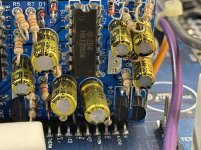
Its funny when it tries to power up, I hear it some stressing through the transformer but twisting it changes nothing. To me it seems like the amp tries to HOT power up about 3 times and then stops as thats what I see it pulling on my bench PS. Currently how it sits it is stuck in protect unless I wait. I tried draining some of the caps but I must not be draining the right one; because then I can probably get it to power up correctly for a few minutes or so. Its using TL594 and a new one for me for latch - which is a 14-pin device with 2B4 HA17324 on it. Looks a little slick too not like a normal IC. Looks custom maybe? Manufactured marking looks like a little camera inside of a circle. Thought it was OnSemi but is not.
Anyways, I tried removing Q1 which is an A1038 but that didn't change anything. I thought removing it would help produce a power up while disabling some of the protect circuitry but I was wrong.
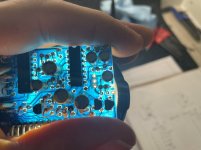
Nothing blown nor shorted on the sides of the board. Board health looks great.
Looks like a newer revision but the revision # is scratched out on the board. This board is not using TIP102/107's tied to the outputs like I've seen in the past on older rev VIII Zeus boards.
TL594
1: 10.00
2: 4.96
3: 4.86
4: 0.917
5: 1.470
6: 3.545
7: 0.003
8: 13.04
9: 0.002
10: 0.001
11: 13.04
12: 12.52
13: 5
14: 5
15: 11.16
16: 6.25
HA17324
1: 11.08
2: 6.25
3: 11.16
4: 12.33
5: 10.20
6: 6.25
7: 11.57
8: 10.68
9: 6.25
10: 10.68
11: 0.003
12: 10.20
13: 6.25
14: 11.08
These readings are the same with Q1 removed.
During the brief power-ups, I am able to sense decent enough rail voltage. I'm measuring about +-54v, +-30v, and +-17v on the rectifiers, and I believe +-54v on the outputs.
There was no DC on the speaker terminals when the amp was able to cold-power up, but once 'charged' I briefly see about +-1vDC on the terminals.
Is there a part I can pull to stop it flying into protect (So that I can do further troubleshooting) or is this one for Stephen Mantz?
Its funny when it tries to power up, I hear it some stressing through the transformer but twisting it changes nothing. To me it seems like the amp tries to HOT power up about 3 times and then stops as thats what I see it pulling on my bench PS. Currently how it sits it is stuck in protect unless I wait. I tried draining some of the caps but I must not be draining the right one; because then I can probably get it to power up correctly for a few minutes or so. Its using TL594 and a new one for me for latch - which is a 14-pin device with 2B4 HA17324 on it. Looks a little slick too not like a normal IC. Looks custom maybe? Manufactured marking looks like a little camera inside of a circle. Thought it was OnSemi but is not.
Anyways, I tried removing Q1 which is an A1038 but that didn't change anything. I thought removing it would help produce a power up while disabling some of the protect circuitry but I was wrong.
Nothing blown nor shorted on the sides of the board. Board health looks great.
Looks like a newer revision but the revision # is scratched out on the board. This board is not using TIP102/107's tied to the outputs like I've seen in the past on older rev VIII Zeus boards.
TL594
1: 10.00
2: 4.96
3: 4.86
4: 0.917
5: 1.470
6: 3.545
7: 0.003
8: 13.04
9: 0.002
10: 0.001
11: 13.04
12: 12.52
13: 5
14: 5
15: 11.16
16: 6.25
HA17324
1: 11.08
2: 6.25
3: 11.16
4: 12.33
5: 10.20
6: 6.25
7: 11.57
8: 10.68
9: 6.25
10: 10.68
11: 0.003
12: 10.20
13: 6.25
14: 11.08
These readings are the same with Q1 removed.
During the brief power-ups, I am able to sense decent enough rail voltage. I'm measuring about +-54v, +-30v, and +-17v on the rectifiers, and I believe +-54v on the outputs.
There was no DC on the speaker terminals when the amp was able to cold-power up, but once 'charged' I briefly see about +-1vDC on the terminals.
Is there a part I can pull to stop it flying into protect (So that I can do further troubleshooting) or is this one for Stephen Mantz?
Last edited:
With Q1 pulled, amp SORT of powers up with rail voltage and no DC on speaker terminals, but something isn't quite right at all.
My Gofert bench power supply sounds like its a ruler against a table, bit very softly. The power supply is almost pulsing on/off like 200 times per second and I can hear it like the amp is cycling that fast. The amp is dragging supply voltage down by 0.2v no matter how much amperage I give it (Its idling at 0.8A). This is at 13vDC supply. As soon as I raise supply voltage to 13.2 or higher, the amp cuts off into protect. If I drop the supply voltage to 12v it seems to stabilize.
Waveform on the fet gates is faint and I can tell its oscillating on/off like 200 times per second there also.
I did not but will. It would be an honor to see him post here.
This amp is using proprietary networks (1) ANW5, (2) ANW12, and (2) VARNW. I found ANW12 schematic and both seem to be testing out OK while on the PCB. I know any of these networks tend to be suspects and would like to check them all if I can.
I'm going to test lower supply voltage with Q1 installed next. I have a hunch there.
Q1 installed is a no-go for anything but just the first cold power-up.
I noticed when Q1 removed, if I attach RCAs to inputs from my frequency generator, then the amp stops the 200/sec pulse from my PS, and the waveform on the fet gates stabilize. There seems to be some audio output on the speaker terminals as measured by my Fluke16 set to AC voltage, but as soon as I touch my scope's ground AC coupling to non-bridging terminals the amp flicks into protect. Something is being over-sensitive.
Rail voltage at the outputs is +-17.5vDC, but there are higher rail voltages +-37 and +-54 at the other rectifiers. Its sticking to the +-17.5v set at the moment.
I'm going to message MOER. Thank you
Last edited:
Now even with Q1 removed the amp falls into protect at over 12.5vDC supply. Pin 16 of the TL594 starts to go high above 6vDC. This pin runs through a resistor and then over to the Hitachi HA17324 quad amp connecting to all Vin- pins - 2, 6, 9, 13.
The way this opamp is being used for Latch may be the reason why most pins are running a high positive voltage.... Is this opamp a suspect by chance? All other parts on the PS riser board are testing out OK.
Thank you
The way this opamp is being used for Latch may be the reason why most pins are running a high positive voltage.... Is this opamp a suspect by chance? All other parts on the PS riser board are testing out OK.
Thank you
The symptoms of this amp seem to be similar in what was happening with the amp in this thread starting with about post #22
Pin 8 goes high when I raise the supply voltage just a bit: 0.2v --> 10.2vDC
Pin 10 goes from 4vDC to about 10vDC
hifonics zeus viii transformer...
Pin 8 goes high when I raise the supply voltage just a bit: 0.2v --> 10.2vDC
Pin 10 goes from 4vDC to about 10vDC
hifonics zeus viii transformer...
Last edited:
Pad 3 (A1038 Emitter) connects to R17, a cap, and D5 which are testing good, which then leads out to what is labeled vi on the board, which is the right-most leg bottom of the PS driver board. This then leads straight to pin 7 of BOTH ANW12 networks. Pin 7 connects to pin6 through 10K resistor which is testing -OK- not leaking (I tested the ANW12s off the PCB). Pin 6 connects to Q103/Q203, C2389 center legs (Collector).
C2389 is measuring 100r between base and emitter on both Q103/Q203
C2389 is measuring 100r between base and emitter on both Q103/Q203
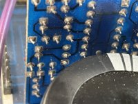
The PS driver board has 17 pins but nothing else is connected to Q2 emitter except what is listed in post #16 from what I can tell. Board removed for checking this.
Putting Q2 back in with one or both Q103/Q203 removed still puts the amplifier into protection.
Q2 removed again.
Now thinking backwards on this it would appear and may be possible that something is putting 10.9vDC on the Q103/203 collectors.
Putting Q2 back in with one or both Q103/Q203 removed still puts the amplifier into protection.
Q2 removed again.
Now thinking backwards on this it would appear and may be possible that something is putting 10.9vDC on the Q103/203 collectors.
Photos of the ps driver board
Q3/Q4 are what’s driving Q2s emitter high.
D5 removed for a minute.
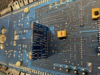
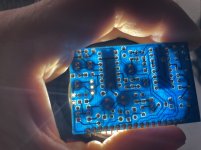
Mounted the ps driver on bottom of board for much easier service.
Q3/Q4 are what’s driving Q2s emitter high.
D5 removed for a minute.
Mounted the ps driver on bottom of board for much easier service.
Attachments
Last edited:
- Status
- This old topic is closed. If you want to reopen this topic, contact a moderator using the "Report Post" button.
- Home
- General Interest
- Car Audio
- Hifonics VIII Zeus in protect