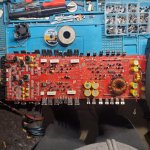
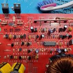
I have a Kicker zx650.4 that has no power at the ic. Several NPN, Pnp 2n4401/4403 transistors have legs have rusted or corrision where they broke the legs right off.
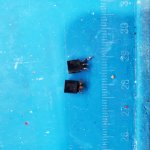
Q12 the silk screen is missing and was wondering which transistor is used here and in which orientation a photo would be helpful of this area.
Q12 the silk screen is missing and was wondering which transistor is used here and in which orientation a photo would be helpful of this area.
Attachments
Q12-2N4401. I don't have a pic of Q12's orientation
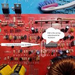
The emitter is tied to the cathode ZD2-1N5225B
The collector is tied to R27-20K
The base is tied to C11-1uF 16v
So you have power to the IC now? Is this IC1-TL494?
Have you checked for shorted outputs?
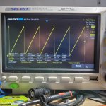
It may be a good idea to remove all power supply mosfets. To disable protection lift D6-1N4148. Check the DC voltages around IC1 and scope pins 5,9,10 for sawtooth and drive waveforms. post screenshots and DC voltages.
The emitter is tied to the cathode ZD2-1N5225B
The collector is tied to R27-20K
The base is tied to C11-1uF 16v
So you have power to the IC now? Is this IC1-TL494?
Have you checked for shorted outputs?
It may be a good idea to remove all power supply mosfets. To disable protection lift D6-1N4148. Check the DC voltages around IC1 and scope pins 5,9,10 for sawtooth and drive waveforms. post screenshots and DC voltages.
Pin 2 of IC1-TL494 is tied to the voltage divider, with the RTH1-10kohm thermistor in the bottom leg. R37-4.32Kohm is the top leg tied to +5v reference.
RTH1 may have failed or a broken leg.
R38-18.2Kohm or RR50-3.01Kohm set the reference voltage at Pin 1 of the Error Correction amp, One of the resistors may be out of value.
If neither resolves the issue post DC voltages around IC1 and post.
RTH1 may have failed or a broken leg.
R38-18.2Kohm or RR50-3.01Kohm set the reference voltage at Pin 1 of the Error Correction amp, One of the resistors may be out of value.
If neither resolves the issue post DC voltages around IC1 and post.
It very difficult to find these by silk screen reference or by tolerance? Some may have been changed previously, and the corresponding silk screen is missing.
Tl494 DC
1.) 3.3
2.) 3.5
3.) 4.7
4.) .001
5.) 1.463
6.) 3.328
7.) .001
8.) .001
9.) .002
10.) .002
11.) .001
12.) 13.76
13.) 4.926
14.) 4.926
15.) 4.926
16.) 12.61
Tl494 DC
1.) 3.3
2.) 3.5
3.) 4.7
4.) .001
5.) 1.463
6.) 3.328
7.) .001
8.) .001
9.) .002
10.) .002
11.) .001
12.) 13.76
13.) 4.926
14.) 4.926
15.) 4.926
16.) 12.61
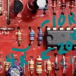
R38 is wrong resistance should be 18.2Kohm.
I attached the photo you sent. RR50 may be one of the two I pointed out.
It appears someone may have changed them out and upset the ratio, You should have ~ .7 volts on pin 1 TL494, not the 3.3 volts you posted.
Check to see if R38 is tied to one of the two resistors and pin 1. When you replace resistors, they won't need to be the exact values, but maintain the same 5 to 1 ratio.
Attachments
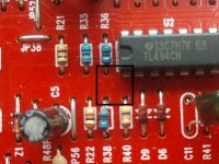
Don't worry about R40- 47Kohm.
The resistor in location R38 pictured is a 200 Kohm based on the color code.
The two resistors you marked 10K and 4K aren't even close to the color codes. Have you removed all three and measured out of circuit?
Also, R38 ties to RR50, R40 and pin 1 TL494 only. You will have to trace Pin 1 to R38 then another resistor that is not R40. Once you've found it, it has to be RR50. RR50 needs to be 5 times smaller than R38. So, you will want to use ~20k-R38 to ~4k-RR50.
I will try to find a blank board for ZX650.4 with the silk screen intake.
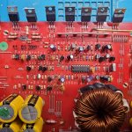
For now I've attached a good board with the silk screen intact. The square shows the node of the three resistors and pin 1.
I will need to find a schematic that shows R36 and verify that it is a 3.01 Kohm resistor. My photo is a fuzzy and I not sure what the color codes are to verify.
Based on your photos R38 looks out of place and I'm fairly certain that is not the original stuffed resistor.
Bare with me, I need to examine the amp I have before I can give you a definitive answer. I'm afraid we are working in the dark, and changing parts will confuse the issue even more.
Attachments
Okay, sorry for the confusion. I was working off of an older or pre production schematic.
R35-3.6 Kohm
R36-11 Kohm
R38-3.01 Kohm
R40- 47 Kohm
RTH5-thermistor 10 Kohm
U2-TL494
Pin 1 should read ~1v dc from power ground
Pin 2 should read ~3v dc from power ground
If you R34,35,38 are replaced with approximately the values listed and RTH5 is intact this should resolve the shutdown issue.
If there are other resistors that you may have replaced or question their value, let me know and I can identify.
- Home
- General Interest
- Car Audio
- KICKER zx650. 4 No power transistor help