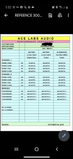
Hi picked up this very clean ss reference 300sx today. It’s got a modified power supply section, and came with a re-birth sheet attached. Does anybody have a schematic so I can just kind of check this one over parts comparison from original? This Amps seems to have different bridge/rect diodes possibly different fets different caps than original. And the rail voltage runs +\- 28 in high power, +-22.5 in high current mode. Otherwise it works thus far.
Thank you
Thank you
Attachments

Without taking the board out of the sync; I've noticed the following differences from that schematic.
F1: 30A Fuse vs. original 20A
C45-C47: (2)35v3300uf vs. (4)25v1000uf
C34-C57+C713-C714: (6)16v3300uf vs. (6)16v2200uf
4xGate resistors are all 10ohm vs. original 47ohm
I don't know what the FETs are since its sandwiched in and a working amp, but I can tell those were replaced for sure. Same with the 12x Rectifier diodes.
Since the amp is getting to +-28vDC rail there may be other modifications here-in, since originally this amp was only every to be less than +-25vDC by the original rail cap ratings.
Amps x Volts x Efficiency
30A x 14v x 0.55 = about 230watts, assuming the 30A fuse blows at 31A...
So, does the re-birth sheet hold some truth or not?
The fuse tells you almost nothing. If you want to know the power output, drive the amp into a dummy load, measure the pre-clipping output voltage and calculate the power.
Fuses don't blow at 1 amp over their rating. You can have surges double their ratings and they won't blow. There are curves published for virtually every type of fuse that tells you what to expect time vs opening for various current levels.
I don't see any regulation so the rails likely vary with the 12v supply input voltage.
Unless they added turns to the transformer, the rail voltage will be about the same as OEM. The diodes they used may be slightly more efficient but that's not going to make much of a difference.
Increasing the value of the caps will do very little unless the designer was incompetent.
In situations where the caps are failing from excess ripple current, going to a higher voltage can reduce the ESR which can make them more reliable.
I completely follow and agree with you on everything. At the end of the day who really knows about this little amp. Sounds great on the bench after cleaning up the notorious ss switches. I have a set of these reference amps 300/700/1000 which are destined for my truck install. I thought about sending to bigdwiz for some new dyno videos.
Question for you though on that schematic you posted... unless the 300/300s is different than this 300sx, shouldn’t c44-c47 be 35v originally? I saw a clear photo online of a similar 300sx and it had original 35v1000uf rail caps x 4. Also it had a 30a fuse.
Question for you though on that schematic you posted... unless the 300/300s is different than this 300sx, shouldn’t c44-c47 be 35v originally? I saw a clear photo online of a similar 300sx and it had original 35v1000uf rail caps x 4. Also it had a 30a fuse.
Last edited:

Revisions don't make it onto diagrams that have already been distributed.
The voltage may have been borderline so they increased the voltage ratings on the caps. A 25v cap isn't going to explode at 26v. Most have a fair bit of tolerance for surge voltage. The following is a datasheet that shows surge voltage.
https://www.mouser.com/datasheet/2/88/380LQ-526534.pdf
At what 12v supply voltage does the voltage across the rail capacitor exceed 25v?
At anything over about 13vDC, the rail voltage exceeds 25v. I don't have the greatest of PS units here so I cant vary the supply very well. I can eigher supply 12.6v, 13.5v or 14.4v. At 14.4, the rail voltage is +-29v.
Is this amp supposed to have a regulated or un-regulated power supply? I don't have my scope anymore. If by design then ok. If this was a modification... then cool?
In other news, I cant get all the switches and gain pots to clean up well enough for sustained use so I'm going to pull the board and replace all faulty devices. Since this and the other amps are also going to get some refreshments I'm going to take the plunge and replace all TL07x opAmps with lme497x0 for SQ. I know I've got a little disclaimer coming for that one lol. Thanks Perry
On this amp, I'm wanting to change out U4, an NE5532 with an LME49720 which is a high fidelity grade OpAmp. I know its not necessarily designed to work just like the 5532, but its what I have available and a direction I want to move this and other amps to for higher SQ. With U4 being first in-line at RCA-inputs I'm definitely interested. I understand that subbing TL07x with LME497x0 is decent fit for these amps, just not sure about replacing the 5532.
What does the Class A 3.0 use for it's single Quad-Opamp?
The biggest difference seems to be the input bias current rating, 800nA vs 10nA.... But thats actually in the 10thousandths of milliamp range.
Thank you
https://www.ti.com/lit/ds/symlink/n...43224&ref_url=https%3A%2F%2Fwww.mouser.com%2F
https://www.ti.com/lit/ds/symlink/l...yCh2i_w4XEAAYASAAEgI_YPD_BwE%26gclsrc%3Daw.ds
Last edited:
D17 and D18 are used as +-16v regulator devices. The schematic doesn't give a part number and hard to tell what these are on the board. What are these diodes?
I'm thinking they may be 1w or 5w 16v Zeners. I may need to replace these w 5w or a pair of 5w per the power draw concerns of the LME op-amps.
Thanks
I'm thinking they may be 1w or 5w 16v Zeners. I may need to replace these w 5w or a pair of 5w per the power draw concerns of the LME op-amps.
Thanks
Precisely what problem are you having with the sound quality of the original op-amps?
I think you're confusing input current to the op-amp with supply current.
Even if the new op-amps would draw more current, they would take some of the load OFF of the Zener diodes in this configuration.
I think you're confusing input current to the op-amp with supply current.
Even if the new op-amps would draw more current, they would take some of the load OFF of the Zener diodes in this configuration.
No real problem at all actually with the opamps, though I didn’t like the floor noise of this amp/5532. I’m going to replace all the tiny 16v4.7uf caps for audio grade ones as well given age, some noise, and piece of mind in having some new caps on the audio path. I’m really just a tinkerer looking to make some improvements if not in the amp then in my own mind.
I understand that sometimes different opamps esp certain OPAxxxx can be more power hungry than standard and since this amp uses Zeners instead of synced regulators thought it might be some issue with adding any power needs of higher fidelity opamps X 4 of them. If the power draw is mainly on the input and not supply then maybe the zeners aren’t a concern.
Thinking forward to this as a design change - 1w vs 5w 16v zener - was thinking to myself more watts would add stiffening buffer into the 16v nanny circuitry.
Last edited:
Thank you. I'll put this amp back together once I get some parts, and monitor the voltages and temperatures at high gain<s> across D17, D18, R89 , and R90. Its worth me noting that R89 and R90 are actually 391ohm 2w resistors whereas the schematic shows Soundstream had planned them to be 220ohm 1w. These components were never replaced afaik.
This is a 2-way soundstream switch from the depths of hell. Why this particular switch with so many little connections was chosen is beyond me. It’s 4 switches in one. Insane. On this 300sx it’s the on/off switch for AirBass.... what a waste. My 1000sx has a single little switch for AirBass. Like anyone ever used AirBass right? On a 300sx? Kidding?
This switch is junk and not replaceable from what I’ve found. Not really worth the time and so ive just bypassed it to permanently disable AirBass on the PCB.


This switch is junk and not replaceable from what I’ve found. Not really worth the time and so ive just bypassed it to permanently disable AirBass on the PCB.
Last edited:
- Status
- This old topic is closed. If you want to reopen this topic, contact a moderator using the "Report Post" button.
- Home
- General Interest
- Car Audio
- Soundstream Reference 300sx