Hi guys,
Got a Soundstream Picasso P1.1500d, but is has a defect in (I quess the power supply) which I could not fins.
The amp had burned power supply fets on one at least one transformer.
There were 2 faulthy output fets as well, so I quess thats where the main problem was in first case.
I took out all the fets, included the rectifiers. Put some better IRF3205's in, but the power supply (I suspect) is making a pretty loud ticking sound (frequency of the ticking becomes higher when I apply more current).
The PWM drive to the gates are ok without PS fets in.
Wiggling on the transformer winding does not help, and it actually reads OK (comparing both transformers, they have 8% tolerance with eachother)
Anybody has an idea?
Attachments
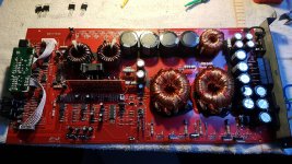
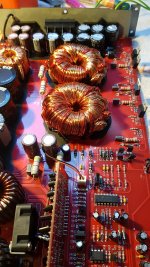
Every transformer has 2 banks with 2 fets on each of the banks. The push banks from both transformers are connected with the same gate drive transistor, and both pull banks have the same gate drive transistor.
From both transformers, the same banks heats up (not sure if it is the push or the pull bank). Only the PS fets from both banks on the right side of each transformer heats up.
When I apply a maximum current from 2a, the ticking is about once per second (1Hz). When I apply a maximum from about 7a, it ticks about 7-8 times per second (8Hz)
The ticking noise seems to come from the transformers, but it's hard to locate.
Check the drive with a loading capacitor (FETs out of the circuit).
I don't understand your use of push and pull. This is a push-pull power supply. Both banks are identical. One bank has it's FETs driven on then the FETs for the other bank are driven on. The two banks are never on at the same time.
Is the drive signal interrupted on the output pins of the SG3525 when it's ticking?
I try to describe it more clearly. The power supply fets from left to right:
(Left transformer fets) fet 1, fet 2, fet, 3, fet 4 (right transformer fets) fet 5, fet 6, fet 7, fet 8.
Fet 3, 4, 7, 8 share the same gate drive transistors (those are the only ones which heat up)
Fet 1, 2, 5, 6 share the same gate drive transistors (those stay cool)
The output of the SG3525 is not building a PWM. It tries to, but it directly shuts off. A tick is produced at the same time.
What do you mean with loading capacitor?
In the future, use the circuit board designations to refer to the various components.
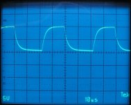
When checking the drive, the drive may look OK because there is no load (as there would be with the FETs in the circuit).
Connect a small capacitor (best in the range of 0.1 and 0.01uF) across the gate and source pads of the PS FETs. You should see something like the attached waveform. This was taken using a 0.047uF. Do this with no FETs in the circuit.
If you have the tutorial, it's covered on the Tech Tips 9 page, item #23.
Attachments
- Status
- This old topic is closed. If you want to reopen this topic, contact a moderator using the "Report Post" button.
- Home
- General Interest
- Car Audio
- Soundstream picasso p1.1500d power supply issue