Does anyone have a schematic for a kicker zx1000.1? This one is the 2005 edition. Came in with blown outputs. Replaced them and checked everything out on low power. All was ok.
Did a high power test and Q106 and Q108 (output transistors) blew again.
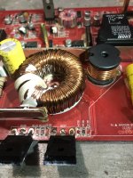
I replaced one of the outputs with one I had here. Now with no load once again, I can get the max rail to rail on the speaker terminals when turning up the gain. Once I connect a load I don’t get very far and the speaker outputs go straight to square. Is there a common problem with these amps? Before I started my test, the output inductor was sort of loose. I used some E6000 on a spot on the bottom to hold it in place. What did I miss?
Did a high power test and Q106 and Q108 (output transistors) blew again.
I replaced one of the outputs with one I had here. Now with no load once again, I can get the max rail to rail on the speaker terminals when turning up the gain. Once I connect a load I don’t get very far and the speaker outputs go straight to square. Is there a common problem with these amps? Before I started my test, the output inductor was sort of loose. I used some E6000 on a spot on the bottom to hold it in place. What did I miss?
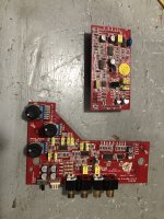
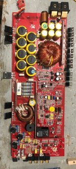
Post pics of the board, overall with and w/o preamp and class D card. Sorry,Kicker policy does not allow me to hand out schematics.
It's possible a loose connection of the output inductor caused the mosfets to blow.
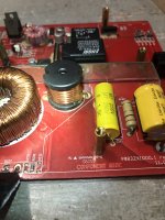
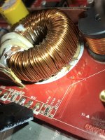
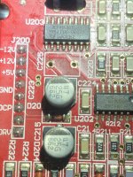
Inspect the output inductors L100 and L101. Particularly L100-signs of delamination, hotspots, or cracked discolored core.
What are the output mosfets?
It's possible a loose connection of the output inductor caused the mosfets to blow.
Inspect the output inductors L100 and L101. Particularly L100-signs of delamination, hotspots, or cracked discolored core.
What are the output mosfets?
I'm not the first one to repair this amp I can tell. The last repairer did not place the fets properly which put a lot of strain on the pads. Once I hit them with heat, well, you know the rest.
The outputs were IRFP4229's
I have attached the requested images. L100 looks alright. I pulled the silicone type glue from the center in order to desolder the inside lead. I measured the inductance at 83uH. The core is not visible without removing the inductor and disassembling - which I'm not even sure if I have to yet. How can I test this puppy?
Attachments
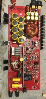
Could I use IRFP264’s as outputs in this amp? I wonder why the original repairer used the wrong ones...
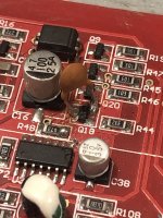
Also, why was the ceramic cap added to Q18?
Yes the IRFP264 is the correct Mosfet. The KX1000.1 original had FQA44N30 and it was decided to use the 264 early in production. Not sure why.
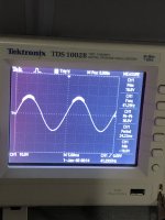
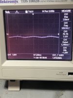
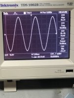
I've installed the IRFP264 fets in this puppy. When using my bench power supply (no batteries yet), I get this weird scope pattern at the speaker output (with dummy load attached). It starts off smooth, but as the supply starts to get near 10A or so, it starts to look like this. It almost looks like distortion, but distortion usually shows up on both the top and bottom.
Is this simply noise being induced from my power supply? I am using a Kenwood head unit with my iphone running a 40hz signal into the USB port. At this point my power supply is putting out about 14A of current.
Is this simply noise being induced from my power supply? I am using a Kenwood head unit with my iphone running a 40hz signal into the USB port. At this point my power supply is putting out about 14A of current.
Attachments
Rail voltage is @ +83.7V and -83.7V
Audio header: J303
Pin 1 (Out) - 0.515V
Pin 2 (V.C) - 10.15V
Pin 3 (-12V) - -11.45V
Pin 4 (GND) - 0V
Pin 5 (+12V) - 11.41V
Class D Header: J200
Pin 1 (-12V) - -11.48V
Pin 2 (+12V) - 11.44V
Pin 3 (+5V) - 4.970V
Pin 4 (GND) - 0V
Pin 5 (GND) - 0V
Pin 6 (OCP) - 4.970V
Pin 7 - 0V
Pin 8 (+DRV) - 4.323V
Class D Header: J201
Pin 1 - 0V
Pin 2 - 0V
Pin 3 (IN) - 0.518V
Pin 4 - 0V
Pin 5 - 0V
Pin 6 - Flickering voltage - Rail to rail with scope
Pin 7 (SFB) - 0.001V
Pin 8 (-DRV) - 4.371V
One weird thing I found, but apparently is normal, is that on U202 (LM361), pin 6 has 11.41V on it. According to the datasheet for it, it's supposed to be -V. When checking the rest of the output pins, they all look to be OK with a square wave that swings from 0V to +5V. Pin 1 has 11.41V on it also.
Also while taking these voltages, the output inductor (L100) climbed to about 51C. Isn't that a bit warm for just idling? The amp was idling with a 4OHM dummy load connected. The HU was connected as well with the volume all the way down and no signal applied. And to confirm, my grounds for the HU are the same as my bench top power supply.
Pin 6 should be -12 volts. You may have reversed your meter leads.
L100 does typically get hot at idle. There should be a thermal pad attached to the cover, to thermal couple the inductor.
J201-Pin 6 is the audio In pin- With out audio you should have nothing. What do you mean Rail To Rail flickering voltage? Post a screen shot. What does the audio look like at that point? Also post a screen shot.
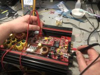
Firstly, when I'm doing my testing, the power connection of the amp is at my left. There's no pin number designations on the class D card or the audio card, so I'm naming the pins from top to bottom....
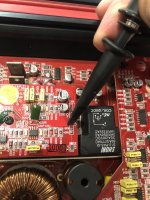
I have included an image of myself checking for -12V @ U202 - Pin 6. I can assure you that my meter arrangement is correct. (Yes I double took my connections when I saw two +12V's on the same IC)
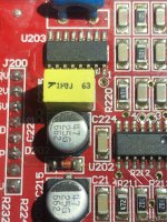
Also, I have desoldered and removed the capacitor that couples both the -12V and +12V's together. I have included an image of the trace that shows a direct connection from the +12V to pin 6. This is why I basically figured that might be normal to have +12V on a -12V connection at the IC. The capacitor measures 1050nF so I'm going to assume it's OK as well.
I have included an image where I'm checking what I think is Pin 6 when looking at the class D card from the top to bottom. That pin is unmarked. It has rail to rail switching voltage on it - which I have included an image of. When I use my multimeter, it flickers from 0.001V to 0.002V somewhat rapidly.
Finally I have included an image of what the J201 pin marked IN looks like with a 60Hz signal from my iPhone to a Kenwood HU. Without an audio signal, it just goes to flat. The signal appears to start at around -0.500V or so.
Hopefully this is enough information to help me make sense of what's going on. As far as U202 having -12V @ Pin 6, I just don't understand how that could be possible given the fact that it's trace is directly connected to the +12V header pin.
Lastly, thanks for helping me with this one. I really appreciate any and all help. My next move is going to be cleaning the trimmer pots and switches. Maybe that's causing a problem...
I have included an image of myself checking for -12V @ U202 - Pin 6. I can assure you that my meter arrangement is correct. (Yes I double took my connections when I saw two +12V's on the same IC)
Also, I have desoldered and removed the capacitor that couples both the -12V and +12V's together. I have included an image of the trace that shows a direct connection from the +12V to pin 6. This is why I basically figured that might be normal to have +12V on a -12V connection at the IC. The capacitor measures 1050nF so I'm going to assume it's OK as well.
I have included an image where I'm checking what I think is Pin 6 when looking at the class D card from the top to bottom. That pin is unmarked. It has rail to rail switching voltage on it - which I have included an image of. When I use my multimeter, it flickers from 0.001V to 0.002V somewhat rapidly.
Finally I have included an image of what the J201 pin marked IN looks like with a 60Hz signal from my iPhone to a Kenwood HU. Without an audio signal, it just goes to flat. The signal appears to start at around -0.500V or so.
Hopefully this is enough information to help me make sense of what's going on. As far as U202 having -12V @ Pin 6, I just don't understand how that could be possible given the fact that it's trace is directly connected to the +12V header pin.
Lastly, thanks for helping me with this one. I really appreciate any and all help. My next move is going to be cleaning the trimmer pots and switches. Maybe that's causing a problem...
Attachments
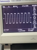
I cleaned the trimmer pots and switches. I powered the amp up with a 60hz signal and my output cleaned right up. The sweep that I have included a photo of, is clean and my amp is drawing 18A of my power supplies 20A output. I'm happy with that.
I am however concerned that I have a +12V in a spot that should have -12V. Also I checked the audio at the IN pin on J201, and it still starts out at -0.500V or so.
Lastly, the cover of the amp does not have anything attached to it to cool off the output inductor. What could I put there?
I am however concerned that I have a +12V in a spot that should have -12V. Also I checked the audio at the IN pin on J201, and it still starts out at -0.500V or so.
Lastly, the cover of the amp does not have anything attached to it to cool off the output inductor. What could I put there?
Attachments
From everything you've said, it appears the amp is working. Have you done any audio testing?
I'm not sure why your seeing +12 volts on Pin 6. I'll take another look at my notes.
I was mistaken about the thermal pad for this amp. I was thinking of the ZX15001. The inductors run hot at idle, but should not cause an issue.
I'm not sure why your seeing +12 volts on Pin 6. I'll take another look at my notes.
I was mistaken about the thermal pad for this amp. I was thinking of the ZX15001. The inductors run hot at idle, but should not cause an issue.
I checked my notes. There should not be +12 volts on Pin 6 of U202. C225-1Uf cap is a decoupling and blocks +12 volts from the -12 volt trace to Pin 6.
Is it possible that J200 pins or traces that carry the +/-12 volts have become conductive? Check for continuity between pins and be sure you have -12 volts with and without class D board installed.
Is it possible that J200 pins or traces that carry the +/-12 volts have become conductive? Check for continuity between pins and be sure you have -12 volts with and without class D board installed.
I have not yet put a speaker on this amp and put higher power to the amp until I get this +/-12V thing sorted out. It does however put out a nice 60Hz signal when put into the RCA's.
So I checked the +12V and the -12V from the grounds at J200. With the class D card installed and not installed I get the same readings. When I check for -12V at the U202 pin 6, I get +12V. I checked for continuity between the +12V and the -12V at the header - there's no continuity. I removed C225 and checked it again and it's checking out at 1051nF. I even reversed it when I reinstalled it. Still getting +12V at U202 pin 6.
I have included a few more images of the traces that lead up to those respective pins. According to the datasheet for the LM361, yes pin 6 should get -12V. However, when looking at the foil side of the class D card, pin 6 and pin 1(-12V and +12V) are directly shorted together. So really, pin 1 which is supposed to get +12V, is actually getting it from the -12V pin 6 designation...
Unless my understanding of electricity is completely messed up (which at ~11pm at night it could be - long day! lol), then it usually follows the path of least resistance... Without a diagram, I'm not too sure where else pin 1 would get its +12V from right at the moment. It looks to be going from pin 1 to C213, and so on... From what I can tell and by checking continuity, those traces are in good shape. When checking from U202 pin 1 to pin 6, I get a direct short, just as the back of the class D card traces illustrate.
Attachments
It's coincidental that the via carrying the -12volt rail is adjacent to Pin 6-U202, and if you look closely you will see they are not attached. You can verify that with an ohmmeter check between the via and Pin 6-U202. I've attached pic's of a board top and bottom side, I have on hand.
MatthewS suggestion is a good one and will definitively determine what Pin 6 is seeing.
MatthewS suggestion is a good one and will definitively determine what Pin 6 is seeing.
Attachments
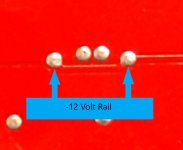
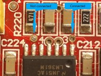
Correction: The trace I label -12 volts and connected to Pin 1 is +12 volts.It's coincidental that the via carrying the -12volt rail is adjacent to Pin 6-U202, and if you look closely you will see they are not attached. You can verify that with an ohmmeter check between the via and Pin 6-U202. I've attached pic's of a board top and bottom side, I have on hand.
MatthewS suggestion is a good one and will definitively determine what Pin 6 is seeing.
- Status
- This old topic is closed. If you want to reopen this topic, contact a moderator using the "Report Post" button.
- Home
- General Interest
- Car Audio
- Kicker ZX1000.1 11.29.2005