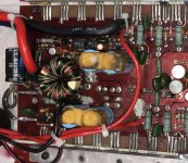
So last night I went to install some POT's on one of my 225's that just had resistors in place when I bought it. After that I figured I'd redo the wiring as it was a hack job but the amp worked. In the process of redoing the power wire I seen a spark go through the power supply and now I'm blowing fuses  . Just wanted to know before starting the troubleshooting process what the issue may be? Nothing was hooked up obviously but did I cause a ground?
Thanks in advance,
Paul
. Just wanted to know before starting the troubleshooting process what the issue may be? Nothing was hooked up obviously but did I cause a ground? Thanks in advance,
Paul
I unsoldered the old wire, stripped it back and put it through the circuit board. It was just laying on top. When I went to being soldering I seen a spark go through the power supply and heard a small pop sound maybe? Hard to explain because I've done many repairs and never experienced this
If the power wires were not connected to a power source, the spark was likely nothing more than capacitors discharging.
It could have damaged a component that's not likely. It's more likely that you have a solder bridge somewhere that's causing the short.
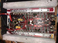
Post a photo of the board in your amp.
To upload photos click the following:
Go Advanced
Manage Attachments
Browse
Upload
Repeat as necessary
Preview post to see how the post will look.
Click Submit Reply to send it to the forum.
It could have damaged a component that's not likely. It's more likely that you have a solder bridge somewhere that's causing the short.
Post a photo of the board in your amp.
To upload photos click the following:
Go Advanced
Manage Attachments
Browse
Upload
Repeat as necessary
Preview post to see how the post will look.
Click Submit Reply to send it to the forum.
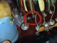
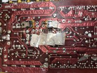
Ok I ended up going back over the board. I'm no longer blowing fuses but I'm only getting power to 3 legs on the power supply. I cleaned up some wiring on the two legs you'll see near each other that looked like they were just soldered to the board. I also notice that there is a lead going to 1 leg that connects to a resistor that is on the bottom of the board. Basically I need to get power to the rest of the legs and I think it'll work again.
Attachments
Various notes...
In these old amps, the capacitors actually need to be replaced. Before you change any, I'd like to know (would be helpful to others) which ones are leaking. To determine which are leaky, heat the terminals. Which emit a fishy sort of smell?
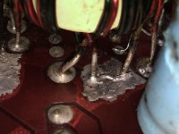
The windings on the transformer appear to have bad connections. They look like they're pulling out. To make the connections as they should be, you need to desolder completely and scrape the wire to bare copper. Tin the leads then resolder them into the board.
On the transformer, there are 4 groups of windings. The 4 windings in each group should read 0 ohms to the others in that group.
Do you have a scope?
Please (and this applies to anyone who needs repair help) use your sig line to list all equipment you have, editing it as equipment changes. Include the model numbers.
Top of page, menu USER CP >> EDIT SIGNATURE
Oscilloscope (yes or no)
Multimeter(s)
Type of signal source (grounded RCA shields preferred).
Soldering iron
Desoldering pump
Power supply
2 ohm current limiting resistor (hollow cylindrical ceramic 100w preferred)
In these old amps, the capacitors actually need to be replaced. Before you change any, I'd like to know (would be helpful to others) which ones are leaking. To determine which are leaky, heat the terminals. Which emit a fishy sort of smell?
The windings on the transformer appear to have bad connections. They look like they're pulling out. To make the connections as they should be, you need to desolder completely and scrape the wire to bare copper. Tin the leads then resolder them into the board.
On the transformer, there are 4 groups of windings. The 4 windings in each group should read 0 ohms to the others in that group.
Do you have a scope?
Please (and this applies to anyone who needs repair help) use your sig line to list all equipment you have, editing it as equipment changes. Include the model numbers.
Top of page, menu USER CP >> EDIT SIGNATURE
Oscilloscope (yes or no)
Multimeter(s)
Type of signal source (grounded RCA shields preferred).
Soldering iron
Desoldering pump
Power supply
2 ohm current limiting resistor (hollow cylindrical ceramic 100w preferred)
Start a new thread if you need help with another amp.
If the tape doesn't want to release (you'll need a Flash capable browser):
http://www.bcae1.com/temp/orionampclamps.swf
Did this amp ever power up?
Did all 16 pads for the transformer have wire in them?
If the tape doesn't want to release (you'll need a Flash capable browser):
http://www.bcae1.com/temp/orionampclamps.swf
Did this amp ever power up?
Did all 16 pads for the transformer have wire in them?
Finally got back to this...
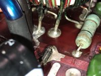
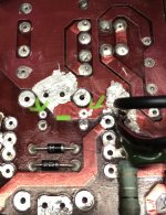
And here is what I found. Pretty sure whoever repaired it jumpered some wire to makeup for missing component. Now I need to know what really goes here. Tested caps and 1 was bad replaced all 4
And here is what I found. Pretty sure whoever repaired it jumpered some wire to makeup for missing component. Now I need to know what really goes here. Tested caps and 1 was bad replaced all 4
Attachments
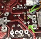
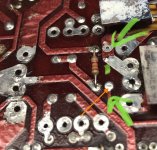
So, a direct connection?
The missing resistor is likely a 120 ohm, 2w (? Confirm that a 2w fits) resistor. Some of the older amps didn't have that resistor installed between the primary and secondary grounds. Having a resistor there will make troubleshooting a bit easier but it's not critical. I'd install one before you return the amp to service.
The missing resistor is likely a 120 ohm, 2w (? Confirm that a 2w fits) resistor. Some of the older amps didn't have that resistor installed between the primary and secondary grounds. Having a resistor there will make troubleshooting a bit easier but it's not critical. I'd install one before you return the amp to service.
- Status
- This old topic is closed. If you want to reopen this topic, contact a moderator using the "Report Post" button.
- Home
- General Interest
- Car Audio
- Orion 225 HCCA 1st Gen Question