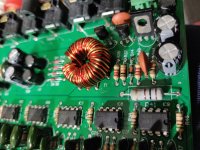
I am trying to repair a Quantum Audio pre-amp that has no output. There is no power to the opamps. There is a small transformer on the board that is getting voltage on it's primary windings and auxiliary windings but there is no voltage bon the secondary windings which feeds some diodes and capacitors which then power the opamps VCC circuit. The remote turn on circuit appears to be working properly as well as the 3 transistors prior to the transformer. What can the problem be? The buck stops at the transformer but I see no sign of a problem or damage...
Attachments

When checking for leakage, you have to use ohms. They may be OK but those diodes failed regularly on other crossovers that used them.
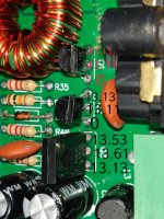
See if this will work, try grounding one end of a 100 ohm resistor and tapping the other end to the base leg of one of the driver transistors (Q1, Q2). Have your scope on one of the primary windings and monitor what happens. Does tapping the base cause the supply to oscillate?
See if this will work, try grounding one end of a 100 ohm resistor and tapping the other end to the base leg of one of the driver transistors (Q1, Q2). Have your scope on one of the primary windings and monitor what happens. Does tapping the base cause the supply to oscillate?
Tested the four diodes on ohms and got 0 ohms in both directions for all.
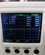
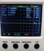
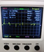
I tapped the base of Q1 and Q2 and got some readings on the scope but only on the 2 outer windings of the secondary ones. There were no reactions visible on the 2 inner windings where they enter the board. There was barely any visible response to a single tap of the 100 ohm resistor connected to ground, so I tapped in quick succession to achieve these screenshots. These were with the diodes resoldered back in.
I tapped the base of Q1 and Q2 and got some readings on the scope but only on the 2 outer windings of the secondary ones. There were no reactions visible on the 2 inner windings where they enter the board. There was barely any visible response to a single tap of the 100 ohm resistor connected to ground, so I tapped in quick succession to achieve these screenshots. These were with the diodes resoldered back in.
Attachments
Last edited:
Make sure that the 2 small windings are not broken.
0 ohms is a direct short and would indicate that all 4 diodes are shorted.
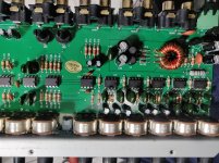
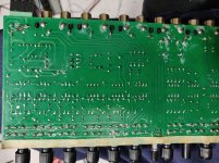
The solder connections on many of the components between the transformer and the closest end of the board look dodgy. Desolder them completely, stand the legs up straight and resolder them.
0 ohms is a direct short and would indicate that all 4 diodes are shorted.
The solder connections on many of the components between the transformer and the closest end of the board look dodgy. Desolder them completely, stand the legs up straight and resolder them.
I removed the transformer and checked all the windings. No breaks, continuity along each lead, and no evident cross-conducting.
I retested the diodes with the meter on auto-ranging. They read 1.6Mohms in one direction, and around 60Mohms in the other.
I removed and resoldered all of the components in the power supply area. I removed and tested the capacitors in the area and they are within tolerance.
Can't get this power supply to start, and don't know what to do next. The only action I see with this is when I touch the board /transformer with my fingers, then I see voltage, as much as +7v on the secondary side and the opamps VCC pins...
Ok, so Q1 and Q2 were defective. I don't have KSP06 so I used MPSA06 as the specs were identical. The power supply powers up but not sure if the output voltage is correct. The supply voltage to the opamps is +29.5v when measured across the + and - legs of the ICs. I am just accustomed to 5v and 15v supplies so this may be correct and normal but I just need to be told that nothing is amiss. I haven't tested for sound or anything either...
- Status
- This old topic is closed. If you want to reopen this topic, contact a moderator using the "Report Post" button.
- Home
- General Interest
- Car Audio
- Quantum Audio QEQ6 pre-amp with no output