You'll have to supply the high-side B+.
Are you referring to the oscillation that's produced by the drive signal (that you'll have to supply) or do you expect it to oscillate at near 100kHz like it does when the amp is functioning?
Are you going to load the outputs to simulate the FETs being in the circuit?
Are you going to try to get it to vary the pulse width?
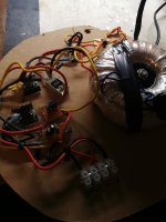
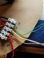
I did it! I made a test bench on a bread board, with a linear (toroidal) power supply generating +/- 30v rails (of which only the negative rail is used). Through a separate winding it is possible to generate the auxiliary voltages of +/- 5v (the voltage of 15v is not needed, because it is used only for the lm293 which carries out the protections) and through a second separate winding with reference to the negative rail, I obtained about 20 volts which I stabilized at 12volt with a regulated lm7812 to power the low side of the ICs. To power the high side, simply connect VS with the negative rail and magically you will also have modulation on the high side. I also thought about building a circuit (using professional services) made specifically to test these boards, but I find it too stressful, because every time I have to test the driver cards externally, I just have to prepare my bread board for the need ( it only takes 10 minutes).
Personally I think that all these tests can also be done with the driver board mounted on the amplifier (without the mosfets) but hey, you're right, because the amplifier runs very high voltages which in case of problems can damage the board. Also on the amplifier, generating the power for the high side, could trigger unwanted protections. Most importantly, if you take apart a driver card to repair it, right after you do, you'll want to try it out, so better try it out before you mount it on the amplifier.
Personally I think that all these tests can also be done with the driver board mounted on the amplifier (without the mosfets) but hey, you're right, because the amplifier runs very high voltages which in case of problems can damage the board. Also on the amplifier, generating the power for the high side, could trigger unwanted protections. Most importantly, if you take apart a driver card to repair it, right after you do, you'll want to try it out, so better try it out before you mount it on the amplifier.
Hello, thank you for the Information. I have a laboratory power supply, which makes up to 30VDC. So i need only the Voltage regulators. I like to test the boards outside the amp, because i dont like to test with 200V and more. I think it makes it more easy. Ok, i will start to build now.. I will report when iam finished.
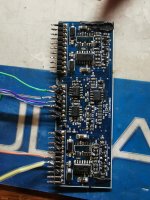
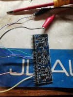
So, i tested, supplyed the +-5V, i have amplitude at pin 1 of the irs... But the IRS wont give out any signal. I have applied the 12V, but nothing happen.
On which pin at the irs i must have which voltage?
I expect:
Pin 3VSS: Ground
Pin 5 Com: Ground
Pin 7 VCC: +12V
PIN 11,12,13 VB, HO,VS :+12V?
On which pin at the irs i must have which voltage?
I expect:
Pin 3VSS: Ground
Pin 5 Com: Ground
Pin 7 VCC: +12V
PIN 11,12,13 VB, HO,VS :+12V?
- Status
- This old topic is closed. If you want to reopen this topic, contact a moderator using the "Report Post" button.
- Home
- General Interest
- Car Audio
- Test class d dwm drive board separately