I have not seen it in working order this ampliefer. I assembled a circuit with transistors and zener diodes, it worked, but the transistors were very hot. Now everything is fine with +-15v. These transistors are heating on the driver board .. I dropped them out and all that are connected to them, everything is ringing well with a multimeter. by the way, the fan speed in this amplifier depends on the input signal level)
Was the only problem with the original circuit that the components were heating up?
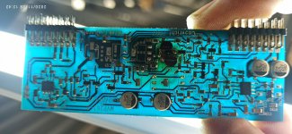
Perry, you have a schematic of this driver? Why, on the basis of the q109 transistor, I have a quadratic impulse, but on the basis of the q128 it is not? Oscilloscope ground to amplifier ground
Attachments
I don't have a diagram for that amp.
Those two transistors may be the same as Q18 and Q19 in the following Sony amp:
http://www.bcae1.com/temp/sony - XM-D400P5_Car Power Amplifier SM.pdf
Those two transistors may be the same as Q18 and Q19 in the following Sony amp:
http://www.bcae1.com/temp/sony - XM-D400P5_Car Power Amplifier SM.pdf
There are a LOT of amps that use this basic circuit design and virtually all of them have problems with drivers overheating. You can see the heat stress in the board in your photo. That's also common in various layouts. In some instances, it's so bad that it causes the board to become conductive.
- Status
- This old topic is closed. If you want to reopen this topic, contact a moderator using the "Report Post" button.