I picked up this amp locally for a song. Didn't even care if it had problems cheap. Only testing was to verify power up without blowing fuses and that bridged it made ok noise.
Tried rigging it in a vehicle and it shows the symptom: 3 channels ok, left front channel has reduced and hashy output. Not dead, trying to pass signal, but no bueno.
Does anyone have any service literature on this model? I googled for awhile and couldn't find a print for this one. I also read that rockford fosgate uses the same architecture across multiple units. This one says pc-4343b by the toroid, if that helps.
Also it seems that previous owner(s) stripped out just about all of the set screws in the speaker terminals. Looking for ideas on what fits or where to source parts. Given a hard choice, I'd rather drill and tap the existing bars out and use larger set screws, rather than wiring up pigtails or some other kludge.
I have plenty of experience in electronic repair. Amateur radio in highschool: earned my technician class license. Enlisted in the navy as an avionics tech. Went aircrew after about a year, qualified for an encyclopedia of stuff. Now I'm a welder fabricator.
Ok so I popped the lid on this one and rigged up an operating table for test & diagnose. For now, I'm using a fluke industrial scopemeter to view waveforms. I don't like it already and will be unpacking the old crt scope soon. Signal source is my phone into RCA jacks on the amp. Load is a pair of klipsch quintet satellites wired in stereo 8 ohms.
Initial impression is I'm following up on a previous repair. Looks like tech swapped out the whole mesha assembly on the side with the issue. Current sample resistor smoked and changed, along with a couple of SMD resistors by it. HV supply is good, and no offset voltage on speaker output terminals.
After briefly working fine (maybe 10 minutes), the issue showed up. At low volume, everything sounds great. Kick the volume up to above 85-90 dB and the left channel can't hang. Top half of the output is collapsing.
You didn't really ask any questions so I don't know if you're asking for help but when you do, include the circuit board designations for the components that are mentioned.
If the speakers are of any value, insert a 100uf bipolar (or equal) 100v capacitor in series with them. Many amps drive full rail to the speakers when they fail.
When you note levels, use voltage. Decibels are meaningless unless referenced to something else.
Does the defective channel drive symmetrically to the rails for that 10 minutes and then suddenly collapse?
Does being loaded/unleaded make a difference.
It's hard to get used to an LCD based scope after using a CRT scope. Handheld scopes can be easier to use when the reference isn't ground but using a mains powered scope in differential mode isn't difficult to set up and can give a much better display of the waveform.
I hear you. I trained and practiced on crt scopes for 20 plus years. The scopemeter has a lot of cool gimmicks and is super portable and durable. It works great on static and pulsing waveforms. Not so great on dynamic, real time audio. The slow refresh rate is frustrating!
I didn't get a lot of bench time on the unit the first round. It was late, and the loud nonlinear sounds summoned she who must be obeyed. I got shut down.
I didn't get a lot of bench time on the unit the first round. It was late, and the loud nonlinear sounds summoned she who must be obeyed. I got shut down.
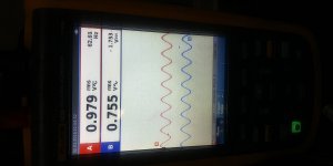
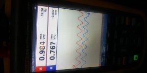
Ok, had a little time to get some tests in. The issue is indeed load dependent. No load, everything look fine. Bigger conductance, earlier issue appearance. It also seems to be frequency dependent as well. The monster comes out above about a volt RMS on the left - terminal at 8 ohms in multiples of about 55-65 hz. Not dependent on input signal vs gain knob.
So tracing signal, I found that the LF_CORE signal stays clean at the preamp side no matter what. This can be seen at the C114 side of R163. On the other side of R163, mayhem. Following the Q111 side of the circuit.
So tracing signal, I found that the LF_CORE signal stays clean at the preamp side no matter what. This can be seen at the C114 side of R163. On the other side of R163, mayhem. Following the Q111 side of the circuit.
I'm assuming that you're comparing the 100 and 200 series circuits.
Try driving the signal into the 100 and 300 series channels. How do the signals compare on the cap side of the resistor?
The 100 and 300 series channels are a better comparison because both are inverting channels.
On the 100 series channel, try lifting D101 and D102 to see if that makes a difference.
Have you confirmed that all of the source resistors in the 100 series channel are within tolerance?
Ok so I went back through the 100 channel and measured all kinds of components and signals and supplies. The power supply rails are good. Little low because I'm running this amp from an atx power supply, and it's rock steady at about 11.8 VDC. HV rails are +-26 VDC, 17 volt rails are 13.6v and -13.1V. Touched up some questionable solder joints and such.
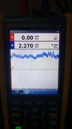
Double checking the lifted diodes, I found that D102 wasn't fully free. So my previous observation was incorrect. Then I lifted D102. Now, when I power up the amp, I have positive voltage on the output lead ( left front -). It's wandering around between 1.5 and 3 volts. See attached picture. Q111 is getting warm as well.
Double checking the lifted diodes, I found that D102 wasn't fully free. So my previous observation was incorrect. Then I lifted D102. Now, when I power up the amp, I have positive voltage on the output lead ( left front -). It's wandering around between 1.5 and 3 volts. See attached picture. Q111 is getting warm as well.
Attachments
The audio circuit functions without D101/102 in the circuit. They clamp the audio in case of over-current through the output stage.
For the regulated voltage, confirm that the voltage measured from output to adjust is 1.25v. If it is, the voltage is likely OK.
What is the measured value of R149 and R136?
Are R137, 138, 150, 151 within tolerance? You will have to desolder one leg of the source resistors to confirm.
For the regulated voltage, confirm that the voltage measured from output to adjust is 1.25v. If it is, the voltage is likely OK.
What is the measured value of R149 and R136?
Are R137, 138, 150, 151 within tolerance? You will have to desolder one leg of the source resistors to confirm.
Yes, all the source resistances were kosher. Measured them right at the beginning. While I was tracing voltages, q111 red plated and got it's source resistor hot. Now q111 is 0.2 ohms source to drain and r149 is well baked and 1 ohm.
I'm guessing that this channel blew out before and previous tech either swapped out the whole mehsa assembly with a donor or put generic parts in it. 200 channel seems to be fine, but I won't know for sure until I get the 100 channel outputs out.
I'm guessing that this channel blew out before and previous tech either swapped out the whole mehsa assembly with a donor or put generic parts in it. 200 channel seems to be fine, but I won't know for sure until I get the 100 channel outputs out.
Didn't touch the bias pot or bump short anything with probes. This unit acted just like a stressed out aged tube amp in need of new glass. Acted fine from cold start. Drove it close to clipping with good sweep and music for a minute or two from cold. Once warmed sufficiently, here comes the distortion. At first, no dc offset. As components devolved, dc offset entered the room. The last hour or so of operation, DC offset was present even at cold start. Towards the end, the dc offset reduced to below a volt. Still hunting, but at reduced amplitude.
I'm not convinced that the problem is the actual output fets. Looking at datasheets, these ones have internal body diodes, so maybe one was breaking down on peaks? I'm thinking more that the output(s) failed because of the lifted failsafe triggers. Nothing to chain him down, so he ran away.
No transistors in the parts bin, plus the reputable supply chain needs a minimum order. If I remove the outputs, shouldn't the phase inverter and current mirrors and such still behave? I saw a decent amount of I don't know what in the signal path. 60 khz spikes riding the audio signal lines. I don't want to assume this is power supply emi if that's not what it is.
- Home
- General Interest
- Car Audio
- Rockford fosgate power 551x