Hi there folks.
I am very new to DIYaudio and this is my very first thread.
Hopefully I would be able to help some guys on this forum")
Unfortunately I got a problem myself today, and after a lot of measuring I really don't know the problem.
I would be very happy if someone has the possibility to help me troubleshooting (even willing to pay for a little 'thank you' for the golden tip)
I am doing a repair on my Boschmann PCH-4882EX class AB amplifier (pretty basic and nothing too special) and this are the following problems + things I have already fixed.
The problem
The amplifier turns on and the GREEN POWER light stays on.
The amplifier is pulling 0.70a idle.
The power supply (pwm) section is working nicely.
The rectifiers do their job nicely too.
The output transistors are fed with the + and - rail voltage.
Unfortunately the amplifier is not producing any sound output
From underneath the amplifier a big (I suspect a GND trace) is going from the transformer to the pre-amp section.
This trace has been burned at several spots (I fixed this already)
What I tried to fix already
I made some clean jumper wires which replaced the trace. I put on some new solder on the traces to thicken them.
When measuring with my oscilloscope there seems to be absolutely zero sound amplification in the pre-amp section.
I suspect it has something to do with the burned GND trace.
Is there anybody who has a clue what could be the problem?
Thanks to all of you
Maxikill97
I am very new to DIYaudio and this is my very first thread.
Hopefully I would be able to help some guys on this forum
Unfortunately I got a problem myself today, and after a lot of measuring I really don't know the problem.
I would be very happy if someone has the possibility to help me troubleshooting (even willing to pay for a little 'thank you' for the golden tip
)I am doing a repair on my Boschmann PCH-4882EX class AB amplifier (pretty basic and nothing too special) and this are the following problems + things I have already fixed.
The problem
The amplifier turns on and the GREEN POWER light stays on.
The amplifier is pulling 0.70a idle.
The power supply (pwm) section is working nicely.
The rectifiers do their job nicely too.
The output transistors are fed with the + and - rail voltage.
Unfortunately the amplifier is not producing any sound output
From underneath the amplifier a big (I suspect a GND trace) is going from the transformer to the pre-amp section.
This trace has been burned at several spots (I fixed this already)
What I tried to fix already
I made some clean jumper wires which replaced the trace. I put on some new solder on the traces to thicken them.
When measuring with my oscilloscope there seems to be absolutely zero sound amplification in the pre-amp section.
I suspect it has something to do with the burned GND trace.
Is there anybody who has a clue what could be the problem?
Thanks to all of you
Maxikill97

Post a good quality photo of the component side of the entire main board and the component side of any driver boards if no one can help.
To upload photos click the following:
Go Advanced
Manage Attachments
Browse
Upload
Repeat as necessary
Preview post to see how the post will look.
Click Submit Reply to send it to the forum.
To upload photos click the following:
Go Advanced
Manage Attachments
Browse
Upload
Repeat as necessary
Preview post to see how the post will look.
Click Submit Reply to send it to the forum.
Thanks for the reply Perry!
The photo's should be attached.
The things you see on the photo's:
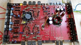
On top of the amplifier you see a cooler. I made this because there are 2 thermal resistors which both read +- 150ohms which get incredibly hot when troubleshooting. I think a big part of the 0.70 ampere idle is going to that resistors.
Just to make sure they won't burn because I am not sure these should be getting that hot.
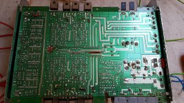
Underneath the amplifier you see the burned GND traces.
Some has snapped of the board and some just got burned.
I made a jumper wire which should be a lot thicker than the trace itself.
The op-amps used in this amplifier are the IL4558S.
From the datasheet it seems like the IL4558S are VCC feeded on both outer legs. All the IL4558S are parallel connected with VCC. My oscilloscope reads 2.11v there.
2.11v as VCC seems pretty low for me so I hoped to find a clue there, because this is the highest present voltage on the OP-amps.
When I follow the 2.11v VCC trace, the VCC is connected with one of the Thermal resistors which get incredibly hot.
On the other leg of the Thermal Resistor my oscilloscope reads 18.4v
When I measure the voltage across this resistor, it is 16.3v.
So when you do 18.4v - 16.3v it makes 2.1V which is feeded to the VCC.
I wonder if this has anything to do with the heavily burned trace and absolutely no sound amplification.
The photo's should be attached.
The things you see on the photo's:
On top of the amplifier you see a cooler. I made this because there are 2 thermal resistors which both read +- 150ohms which get incredibly hot when troubleshooting. I think a big part of the 0.70 ampere idle is going to that resistors.
Just to make sure they won't burn because I am not sure these should be getting that hot.
Underneath the amplifier you see the burned GND traces.
Some has snapped of the board and some just got burned.
I made a jumper wire which should be a lot thicker than the trace itself.
The op-amps used in this amplifier are the IL4558S.
From the datasheet it seems like the IL4558S are VCC feeded on both outer legs. All the IL4558S are parallel connected with VCC. My oscilloscope reads 2.11v there.
2.11v as VCC seems pretty low for me so I hoped to find a clue there, because this is the highest present voltage on the OP-amps.
When I follow the 2.11v VCC trace, the VCC is connected with one of the Thermal resistors which get incredibly hot.
On the other leg of the Thermal Resistor my oscilloscope reads 18.4v
When I measure the voltage across this resistor, it is 16.3v.
So when you do 18.4v - 16.3v it makes 2.1V which is feeded to the VCC.
I wonder if this has anything to do with the heavily burned trace and absolutely no sound amplification.
Attachments
The term 'thermal resistor' isn't really correct. Thermistors are a real component. The 'resistors' that you're likely referring to are simply resistors (can't see them).
The voltage on 1/9 of the op-amps should be approximately 15v. The voltage on pin 5 should be approximately -15v. What's the voltage on pin 5?
The burned traces could be from a shorted transformer, speaker wires shorting to ground or 12v touching to the RCA shield.
The voltage on 1/9 of the op-amps should be approximately 15v. The voltage on pin 5 should be approximately -15v. What's the voltage on pin 5?
The burned traces could be from a shorted transformer, speaker wires shorting to ground or 12v touching to the RCA shield.
Ah yes, my bad.
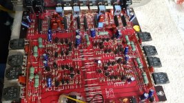
Yes, these are normal resistors. The resistors which I'm cooling now are the same big green resistors which you see at the legs from the output transistors.
To give some more details, the 18.4v on one leg of the resistor seems to be the rail voltage
I measured pins 1/9 and pin 5.
Pin 1 and 9 are measuring 2.11v (with a power supply voltage of 10.6v)
Pin 5 is measuring -0.20v
Yes, no problem.
Attached are some clear photo's of the resistors.
One resistor reads 145.6ohm
The other reads 156ohm (which is connected to the VCC)
Bertje, thanks for your reply.
The glued TO-220 mosfet is used for powering the cooler. So the cooler current is not pulled from the REMOTE but from the 12v+, but it is controlled by the REMOTE. This is not original.
Attachments
Did the Zeners check OK?
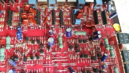
The Diode on the left from the resistor reads 0.00v and 0.01v
The Diode on the right from the resistor reads 0.39v and 0.18v
That readings was in diode settings....
Something was defenitely not good with those zener diodes.
Luckely I had 2 pieces in spare in an other device.
Both has been replaced, and the amplifier is working
The VCC from the opamps is now around 15v stable.
I need to order a single new part and when that part is installed I can fully test all 4 channels and then I let you know or this was the exact problem.
- Status
- This old topic is closed. If you want to reopen this topic, contact a moderator using the "Report Post" button.
- Home
- General Interest
- Car Audio
- Car amp burned GND trace to pre-amp section, replaced but still no sound :(