Picked up an untested 600a4. With my initial test I got an idle current draw of .75A that jumps up to around 3.XXA. I reset the bias pots on all channels and got the idle current down to 1.77A. This still seems a little high considering I get about 1.12A on 800a2 amplifiers.
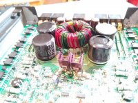
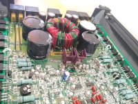
U3 (LM317) and U4 (LM337) are in the middle of the board with their own dedicated small heatsinks, and they are getting painfully hot.
Output sounds okay from all 4 channels during a brief test, and there were no shorted outputs or any other damage I could see, except that the toroidal transformer is mounted so high that it's rubbing and being pressed down by the case cover, forcing the pcb to bend under the pressure. Also, the filter caps aren't looking so great, with one even being dented somehow.
Aside from fixing the transformer so it's not touching the case, and possibly recapping the board, does the idle current draw or U3/U4 heat raise any concern, or am I just paranoid?
Thanks
Attachments
The transformer will obviously have to be lowered towards the board.
The caps may be OK. The tops don't look swollen. The heatshrink isn't a good indicator of the condition of the caps.
If you pull the caps, be VERY careful. If the vias are tight, it's easy to destroy them.
Make sure that the regulator heatsinks aren't touching. They can run hot and survive. They have internal protection circuits that shut them down if they are in danger of failing. The ones in the BD amps operate at very high temperature and only very rarely fail.
If you set the bias pots fully CCW, does the voltage across the 0.1 ohm source resistors drop to 0.000v DC at idle, no load?
The two to the right of the transformer certainly appear to be beyond their useful life. Possibly the near one on the left as well. Do any have appreciable DC resistance (does an autoranging DMM stop at some low-ish value, say a few hundred or k-ohms)?
Do all faculties behave properly? The LM317/337's probably wouldn't suffer from main rail issues, but you'll need to test all the filter and EQ options to be sure one of them isn't drawing extra juice (thus heating the regulators).
Regards
Do all faculties behave properly? The LM317/337's probably wouldn't suffer from main rail issues, but you'll need to test all the filter and EQ options to be sure one of them isn't drawing extra juice (thus heating the regulators).
Regards
Last edited:
The transformer will obviously have to be lowered towards the board.
The caps may be OK. The tops don't look swollen. The heatshrink isn't a good indicator of the condition of the caps.
If you pull the caps, be VERY careful. If the vias are tight, it's easy to destroy them.
Make sure that the regulator heatsinks aren't touching. They can run hot and survive. They have internal protection circuits that shut them down if they are in danger of failing. The ones in the BD amps operate at very high temperature and only very rarely fail.
If you set the bias pots fully CCW, does the voltage across the 0.1 ohm source resistors drop to 0.000v DC at idle, no load?
Regulator heatsinks have a small space between.
With bias pots fully CCW, my idle current draw is 1.2A and I get 000.0mv across each 0.1 ohm source resistor.
I've been setting bias based off a 0.05A increase per channel from base idle current. Is there a better way that I can do with a meter, or is this sufficient?
If you let the amp idle for 10 minutes with no bias, does the heatsink begin to heat up?
0.05A is likely OK. I don't measure the current. I look at the amp meter and adjust to where it just starts to show an increase in current draw.
What's the operating frequency of the power supply?
0.05A is likely OK. I don't measure the current. I look at the amp meter and adjust to where it just starts to show an increase in current draw.
What's the operating frequency of the power supply?
The main heatsink is still cool - all mehsa components are cool. The individual U3 and U4 heatsinks are hot, about 192° and 202° according to an infrared gun.
I don't know how to measure the operating frequency of the power supply. Oscilloscope? Unfortunately, I don't really have the space to keep one.
I don't know how to measure the operating frequency of the power supply. Oscilloscope? Unfortunately, I don't really have the space to keep one.
I haven't pulled the board so I'm not sure I could check the caps for any DC resistance (would that work in circuit regardless?).The two to the right of the transformer certainly appear to be beyond their useful life. Possibly the near one on the left as well. Do any have appreciable DC resistance (does an autoranging DMM stop at some low-ish value, say a few hundred or k-ohms)?
Do all faculties behave properly? The LM317/337's probably wouldn't suffer from main rail issues, but you'll need to test all the filter and EQ options to be sure one of them isn't drawing extra juice (thus heating the regulators).
Regards
I've run through the HP/Full/LP switches and punch bass without any problems or changes.
Ya' know they come in flat screens now, just like consumer TV's ..Oscilloscope? .. don't really have the space ..
")
200 degrees Fahrenheit, right? That is pretty toasty -- warmer than I like -- but a reasonably safe distance from imminent death. Also, not too unusual for modern gear. Once you get the rest of it all nice and peachy, it might give a little extra reassurance if you were to run it for 10 minutes with loads, and the cover just sitting on (assuming that's possible without damage). Then pop the cover and aim the infrared gun -- just to confirm that it isn't 30 degrees worse all buttoned up.
Cheers
Last edited:
To address your other question - Yes, large electrolytic capacitors can be checked (partially -- gross faults at least) in circuit -- assuming your DMM is newer than, say, early 1980's or so.
The Diode range typically goes up to about 2V. DCR is measured using a voltage low enough that semiconductor junctions stay off.
The Diode range typically goes up to about 2V. DCR is measured using a voltage low enough that semiconductor junctions stay off.
Ya' know they come in flat screens now, just like consumer TV's ..
200 degrees Fahrenheit, right? That is pretty toasty -- warmer than I like -- but a reasonably safe distance from imminent death. Also, not too unusual for modern gear. Once you get the rest of it all nice and peachy, it might give a little extra reassurance if you were to run it for 10 minutes with loads, and the cover just sitting on (assuming that's possible without damage). Then pop the cover and aim the infrared gun -- just to confirm that it isn't 30 degrees worse all buttoned up.
Cheers
Yes, °F. Actually got up to around 210° playing one channel quietly with only an 8ohm load, upside-down with the back off (which would be the best case scenario for these independently heatsinked).
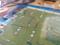
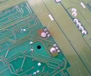
Pulled the board and reworked the transformer down to a reasonable position. Also noted the heat discoloration on the board from the U3 LM317.
Filter caps all read ~400ohm and then gain up beyond 2000+ on either my meter's 2000ohm setting or diode mode.
Filter caps all read ~400ohm and then gain up beyond 2000+ on either my meter's 2000ohm setting or diode mode.
Attachments
-
 IMG_20200827_175718767_copy_1280x960.jpg386.1 KB · Views: 131
 -
 IMG_20200830_134814861_copy_1280x960.jpg296.8 KB · Views: 140
 -
 IMG_20200830_145345490_copy_1280x960.jpg239 KB · Views: 139
 -
 IMG_20200830_152901014_copy_1280x960.jpg309.9 KB · Views: 126
 -
 IMG_20200830_154608015_copy_1280x960.jpg394.6 KB · Views: 141
 -
 IMG_20200830_133903357_copy_1024x862.jpg204.8 KB · Views: 80
The same voltage on pins 1 and 2 indicates that the regulation of the rail voltage is working properly.
The majority of the large capacitors on the B+ or the rails are used to filter high frequency (in the neighborhood of 30kHz) ripple. With a scope, you can get a very good indication of whether the caps are good enough by looking at the ripple on the rail and B+ voltage. It's normal to see ripple that's related to the frequency of audio. The problem is when you see high frequency ripple along with the audio related ripple. This can be very difficult to see on digital scopes. On analog, CRT scopes, it's immediately obvious.
The majority of the large capacitors on the B+ or the rails are used to filter high frequency (in the neighborhood of 30kHz) ripple. With a scope, you can get a very good indication of whether the caps are good enough by looking at the ripple on the rail and B+ voltage. It's normal to see ripple that's related to the frequency of audio. The problem is when you see high frequency ripple along with the audio related ripple. This can be very difficult to see on digital scopes. On analog, CRT scopes, it's immediately obvious.
- Status
- This old topic is closed. If you want to reopen this topic, contact a moderator using the "Report Post" button.
- Home
- General Interest
- Car Audio
- Rockford Fosgate Punch 600a4