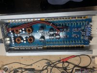
I got this lanzar opti in, amp was in protect. When checked it had shorted transistors (collector to emitter) on the right channel. All output Transistors were replaced.
Amp came out of protect and passed clean audio. When connected to a load, amp went straight into protect.
Checked output transistors and they were shorted (base to collector).
I pulled this attached schematic from another post, the values for the drive section are on point.
I pulled the pre drivers and drivers, all checked ok. Verified resistor values and all were within.
I then soldered in only one transistor per rail, again amp passed clean audio, when connected to a load (8ohm dummy) the amp went straight into protect.
The installed transistors were shorted base to collector.
I’ve compiled a list of components for the drive section to order and have all replaced.
The bias transistor is a C3200, I’m gonna replace those with MPs6521 due to availability.
Has anyone experienced something similar?
Attachments
Arite gents, I got parts in and some time over the weekend.
I rebuilt the drive section for the right channel.
I replaced the drive transistors: C3856 with MJW3281 and A1492 with MJW1302.
I had problems acquiring the bias transistor (C3200) I replaced this with MPS6521 as I found in another post.
C3200 bias transistor
I installed one output transistor per rail and powered up, amplifier passes clean audio, without and with load.
I'm not familiar with the actual calculations for the voltages across the bias transistor, but would the MPS6521 be a reliable replacement given this amplifier has +/- 70v rails?
I tested the amp on two occasions, stopping at approx. 10deg C intervals to check current draw:
- on the first power up I ran it up to 62/65 deg C when I stopped to check the bias current, it went up from 2.4 A to 3.2 A. I had one resistor (R147 equivalent, schematic in post 1) drift a little, it dropped in value from 4.7K to 4.2k. I replaced this resistor with a new 4.7k.
- I powered up a second time, amplifier pass clean audio but now I have 1v dc on the speaker terminals.
I stopped here for today, I didn't mess with Q107 and Q108, would these be a good point to start chasing the DC at the speaker terminals?
You need to refer to the transistors as shown on the 500x2 diagram you posted.
If you don't have a defective component beyond the differential amplifier transistors, a DC fault is likely to be in the differential amplifier circuit. Mismatched transistors for a differential pair is enough to cause the fault.
Does the DC remain the same with or without a speaker/dummy load?
If you don't have a defective component beyond the differential amplifier transistors, a DC fault is likely to be in the differential amplifier circuit. Mismatched transistors for a differential pair is enough to cause the fault.
Does the DC remain the same with or without a speaker/dummy load?
Before I left I got to isolate the DC was in the amplifier section. I removed the input cap and the 1vDC was still there at the speaker terminals.
The DC remains the same with or without load.
I’m hoping it’s not the differential pair, I’ll have to hunt around for replacements for those.
The DC remains the same with or without load.
I’m hoping it’s not the differential pair, I’ll have to hunt around for replacements for those.
- Status
- This old topic is closed. If you want to reopen this topic, contact a moderator using the "Report Post" button.
- Home
- General Interest
- Car Audio
- Lanzar opti 700x2
