Howdy, I used a modified Milbert BaM230 tube car audio amp using a 12V switch mode power supply and car battery, while working overseas many years back...
Hi ! thanks a lot for your very kind and valuable advice. I am quite pleased with my actual preamp that is also remote controllable Visiting the flea markets in my city i was seeing many nice looking car audio amp. Then my idea to try some This in particular costed me about 30USD

I am not sure that it works even if they told me so ... but the price does not buy a kit ... and inside it looks very nicely laid-out Like most car audio amp
They are very nice looking
Also 12V powerful smps are very available. I see some 1kVA units for servers at ridiculous prices ... but i have understood here (Thanks !
) they need skills to be used in home properly and safely But they are gorgeous
I'm using 1/2 of car amplifier for power supply!
Just the smps.
A 220/12V transformer, a bridge rectifier, the smps of car amplifier and a lot of amplifiers! Poor man's power supply!
Hi ! i think that the smps needs a stable (i.e. regulated or battery) 12VDC power supply to work properly ... can it take also a not regulated 17V ?
Depends on the amp.
Some amps have 25v primary side caps and I imagine would be fine, some have 16v caps and are already run on the edge in terms of Ripple current and might let go.
I’ve also got a big transformer ( about 600va ) which rectified and filtered put out about 16v, this drops quite quickly with a load and so amps that draw over an amp or so at idle pull the voltage down to 15v or so. I’ve had good luck so far using it but have only chanced it on amps with 25v primary caps, as mentioned above.
Re 140:
I've never seen such a range of outputs, ever. Look at the date codes. Some were made in 1982. Others in 2002.
Did you write '33' and '36' on the board? <<<<
Re 142:
Car amps can run on a wide range of voltages. The supply doesn't have to be regulated. It just has to be within the range that's acceptable to the amp. Some amps have under/over-voltage protection that ensures that they won't operate outside of that range.
You have to worry about the secondary caps as well. It's somewhat rare to have a regulated secondary on cheaper amps. When the input voltage increases on those amps, the secondary voltage also rises. That can put the rail caps at risk.
The higher secondary voltage will also put more stress on the ±15v regulators.
Re 140:
I've never seen such a range of outputs, ever. Look at the date codes. Some were made in 1982. Others in 2002.
Did you write '33' and '36' on the board? <<<< ...
Hi ! thank you so much for your kind and helpful support
The 33 and 34 were already on the board when i removed the bottom lid.
I guess they were written as a reminder of the parts to be used ... tip33 and tip34 ?
I have already ordered 5 pairs of tip35c and tip36c with the idea of replacing the output tips.
I am still thinking to use Toshiba devices ... just one pair for channel
I will be using a small portion of the power available ... i will buy them from mouser to avoid any issue with fake parts
And i will replace the thermal pads ... i understand they degrade with time
Toshiba? Why?
The parallel parts need to match (no mixing as was done on this amp) to get the best reliability.
I've never heard of the silpads deteriorating. The problem I see is that the new semiconductors won't lay the same (on the depressions/ridges) and that could prevent the best thermal coupling. I have no problem reusing the old pads as long as thermal compound is used.
Toshiba? Why?
to do with just one pair for channel mostly ... member Guerilla told me that some high power Toshibas could work considering that i will be not drawing much power from the amp. And this will simplify the replacement of the originals
Thanks. So there is no reason to use transistors of different powerThe parallel parts need to match (no mixing as was done on this amp) to get the best reliability.
My guess is that they did not have the right bjt and used a more powerful one. I do not have access to the original schematic. But my guess is that they were using 33c and 34c ... two pairs for channel. I do not believe that they were using matched ones.
i see. I am afraid the new ones have a different package. Anyway ... what about using thicker thermal pads like the ones for cpus ?I've never heard of the silpads deteriorating....
High Conductivity Thermal Pad Heatsink GPU CPU Cooling Paste-Gel Silicone H5Z8 | eBay
They come with very different thickness and size ... i love them
I have used for some mods on a media player with great success
Im innocent. I know nothing about transistors
Cheers!
Sorry ! you are right
... i was mixing advices Here is the kind suggestion i got ....
I see a base resistor in your picture and that makes me think that the original transistors might be higher FT as well...try 2sc5200/2sa1943...very cheap ...
Hi ! thank you Mr Dreamth !!!
On this basis i am very willing to try the one 2sc5200/2sa1943 pair per channel option ... also considering that in any case i will be using a fraction of the available power
https://www.mouser.it/ProductDetail...JsPskqkeuaWvssU0W-7G9ajVsq_EUR5gaAiOVEALw_wcB
I am not a subwoofer fan at all (actually i think that this amp must have been stressed in some car audio system ?)
I think that oscillations could be an issue ... i guess the worst thing that can happen is that i fry them ?
Thanks again to All of you
Last edited:
I'm using 1/2 of car amplifier for power supply!
Just the smps.
Which looks suspiciously like a Blaupunkt BPA-260/430. That one is digging pretty far back in time.
Re #149:
Why Toshiba? Why/how would it simplify?
As was stated before, you need to have the parallel output matched so they will share the load equally. The use of transistors with matching date codes is generally good enough.
They were either too cheap or didn't know what they were doing when replacing the outputs and used mismatched parts.
If you are going to replace the insulators, I'd suggest using mica insulators with thermal compound (on both sides of the insulators). I recommend Dow Corning 340 but others will work. I see no problem using the original silpads with heatsink compound.
If you use the original pads, clean them thoroughly to remove any contaminants. Don't lift them from the heatsink unless they're already lifted.
Re #151:
The 2sc outputs require a different biasing than the TIP outputs. They are typically not compatible. If used, the bias will have to be mapped/tracked to confirm that there will be no avalanche.
Last edited:
Hi ! no matching issues for instance ? i had in the very past a home power amp from Nikko brand It was pumping a good bass out of my speakers with only one pair of i think 200W bjts per channelRe #149: Why Toshiba? Why/how would it simplify? As was stated before, you need to have the parallel output matched so they will share the load equally. The use of transistors with matching date codes is generally good enough.
Those were in TO3 package ... but maybe a single 150W pair could work
If they break i will go back to the 2 pairs solution.
The less parts the simpler the design in general
They were either too cheap or didn't know what they were doing when replacing the outputs and used mismatched parts.
If you are going to replace the insulators, I'd suggest using mica insulators with thermal compound (on both sides of the insulators). I recommend Dow Corning 340 but others will work. I see no problem using the original silpads with heatsink compound.
If you use the original pads, clean them thoroughly to remove any contaminants. Don't lift them from the heatsink unless they're already lifted.
Thanks a lot again. I really would like to try the thicker version for computer cpus also because the original are very thin and if i tighten too much the screws the bjts case could be stressed against hard metal surfaces.
I prefer to compress a softer thicker pad. They come in any size and can be cut precisely as needed.
and this stops completely my weird idea. I will use 35c and 36c pairs then. Actually i am waiting to received them. I really hope they are genuine parts and not fake. They should be of the same period ? i will take a pic of themRe #151: The 2sc outputs require a different biasing than the TIP outputs. They are typically not compatible. If used, the bias will have to be mapped/tracked to confirm that there will be no avalanche.
In the meantime i will order the thermal pads
Thanks a lot again
actually i am mostly worried about cracking the bjt body It will get very hot and maybe fragile as well ... of course i will try not to tighten the clamp on it too muchYou cannot, no matter how tightly you clamp the transistors, cut the insulators ...
A thicker and soft thermal pad placed under the bjt (but maybe also above it like a sandwich ?) can decrease the mechanical stress on the bjt body ... more than the original very thin thermal sheet
It will behave like a thermal conductive rubber let's say
Last edited:
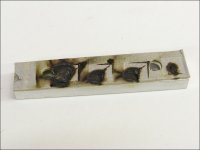
You will turn those clamps into pretzels before you crack the plastic on those transistors. Take one of the old transistors, put it on a smooth-jaw vice and TRY to break it. Then look at the force that you could apply with a thin clamp using a 3mm self tapping screw in soft aluminum.
Look at the clamp from a blown amp. It uses a dense cardboard that's been compressed on the transistors and no damage was done to the transistors. This was a much heavier clamp with much larger screws.
Many MILLIONS of amps have been manufactured using the insulators in your amp. The people who design/build amps for a living thought that they were a good choice.
This is your amp and you use whatever you think is best but the stuff used for computers isn't reinforced, isn't made to withstand the pressure and likely isn't reliable at electrically insulating at the higher voltages present in an amplifier.
Get the amp working perfectly as it was designed and THEN start to experiment.
Attachments

- Status
- This old topic is closed. If you want to reopen this topic, contact a moderator using the "Report Post" button.
- Home
- General Interest
- Car Audio
- Anyone using a car audio amp in a home stereo set-up?