I have a Kicker SX 1250.1 Date stamp on the board says 2004 3 13
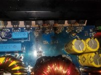
The low voltage rca input on the amp was being finicky, would have to apply pressure on the cables to get it to work properly at times. i decided to take the cover off of the amp to see if i could fix the issue and found some burned MOSFETs in the corner. As far as i know the amp still works, unless it burned as i was taking it apart or right before. They look very damaged. I dont know much about amp repair. Im thinking of replacing all 5 of the IRF3205 transistors in that area.
I dont know much about how amplifiers work.
I dont know which IRF3205 to use, or what else to check/replace.
What kind of thermal tape to use? maybe silicone-rubber?
Any help would be appreciated.
Equipment i have: soldering iron, solder, vacuum de-soldering tool. Car battery. Multimeter. handheld oscilloscope.
Attachments
It is recommended that you replace all ten IRF3205's (Q06,07,08,09,17 & Q12,13,14,15,19) and Q05,Q11-KTA1504GR driver transistors.(Someone may have a good source or substitute for the 1504GR)
Be sure to purchase from a reputable source such as Mouser,Digi-Key, Arrow. Do Not Buy off of Ebay!! The link below for Mouser is a good source for the IRF3205. It's important that the mosfets are from the same batch/tube. The date code should all be the same. Do Not Reuse the Mosfets you pull from this amp!!
Check all the Gate Resistors R16-R20,R22-R26) 47 ohm SMD 1206 footprint.Replace any that are out of value, or play it safe and replace all ten.
Clean up the existing thermal tape and look for tears,perforations or thin spots. You may be able to reuse what is there. Someone else may be able togive you a good source. I don't have one handy, but will check in the next day or two.
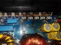
It's best to remove all of the IRF3205's and A1504GR's,clean the board, remove any solder bridges. Once done, check with no power applied and ohmmeter the locations where the mosfets where, between all three legs for low ohms or shorts. I believe you should have 47K ohm across the two outside legs. I've attached your pic marking each mosfet leg.Post your results in the following format.
OHMS
1-2
2-3
1-3
When you have replaced the A1504GR's and replaced any Gate Resistors and the Ohmic checks look good the next step will be to check the Triangle wave and Drive from U01-TL494 which I will explain later.
This amp is going to require systematic and step by step instructions considering the difficulty and your skill level. It can be done but be patient, ask questions and take each step in time and order.
IRF3205PBF Infineon Technologies | Mouser
Be sure to purchase from a reputable source such as Mouser,Digi-Key, Arrow. Do Not Buy off of Ebay!! The link below for Mouser is a good source for the IRF3205. It's important that the mosfets are from the same batch/tube. The date code should all be the same. Do Not Reuse the Mosfets you pull from this amp!!
Check all the Gate Resistors R16-R20,R22-R26) 47 ohm SMD 1206 footprint.Replace any that are out of value, or play it safe and replace all ten.
Clean up the existing thermal tape and look for tears,perforations or thin spots. You may be able to reuse what is there. Someone else may be able togive you a good source. I don't have one handy, but will check in the next day or two.
It's best to remove all of the IRF3205's and A1504GR's,clean the board, remove any solder bridges. Once done, check with no power applied and ohmmeter the locations where the mosfets where, between all three legs for low ohms or shorts. I believe you should have 47K ohm across the two outside legs. I've attached your pic marking each mosfet leg.Post your results in the following format.
OHMS
1-2
2-3
1-3
When you have replaced the A1504GR's and replaced any Gate Resistors and the Ohmic checks look good the next step will be to check the Triangle wave and Drive from U01-TL494 which I will explain later.
This amp is going to require systematic and step by step instructions considering the difficulty and your skill level. It can be done but be patient, ask questions and take each step in time and order.
IRF3205PBF Infineon Technologies | Mouser
Attachments
i contacted littlediode with a request for a quote and they sent me this link.. what do you think?
KTA1504GR Transistor - Buy from Littlediode
also found these on ebay...
5PCS X KTA1504GR SOT-23 KEC | eBay
KTA1504GR Transistor - Buy from Littlediode
also found these on ebay...
5PCS X KTA1504GR SOT-23 KEC | eBay
Last edited:
I am in Fort Lauderdale, Fl.
So i can use
SMMBTA06LT3G ON Semiconductor | Mouser
in place of the KTA1504GR ?
I already ordered 10 47 ohm gate resistors and 10 3205s. I will try to order any additional parts together so i dont get hammered with shipping.
So i can use
SMMBTA06LT3G ON Semiconductor | Mouser
in place of the KTA1504GR ?
I already ordered 10 47 ohm gate resistors and 10 3205s. I will try to order any additional parts together so i dont get hammered with shipping.
retested with q5 and q11 removed.
q6
1-2 ~70K
2-3 starts at 0 and rises as cap charges i guess
1-3 ~70k
q7
1-2 ~129K
2-3 starts at 0 and rises
1-3 ~129K
q8
1-2 ~46K
2-3 starts at 0 and rises
1-3 ~46K
q9
1-2 ~1M
2-3 starts at 0 and rises
1-3 ~1M
q17
1-2 ~46K
2-3 starts at 0 and rises
1-3 ~46K
q12
1-2 ~46K
2-3 starts at 0 ohms and rises
1-3 ~46k
q13,14,16,19 all same as q12
Last edited:
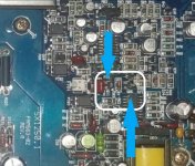
With out getting into the series-parallel connection of the mosfets,gate resistors,R21,R27-47K ohm and the power transformer, Q6, Q7 and Q9 gate resistors are open,out of value or disconnected from the loop.
Check R16,R17,R19 if you haven't already. Once you replace the gate resistors you should get proper readings.
When you have the replacements for Q05 and Q11 and installed them, be sure you have the 47Kohm across the 1-3 for each of the mosfets. At that point You can power up the amp w/o the mosfets and check the drive from Pins 9 & 10 of U01-TL494. I will get in to more detail when you are at that point.
Are there any other parts you suggest i order just in case so i can save on shipping and time later? maybe the TL494 ? TL494CDRG4 Texas Instruments | Mouser ??
U1 is a TL594Are there any other parts you suggest i order just in case so i can save on shipping and time later? maybe the TL494 ? TL494CDRG4 Texas Instruments | Mouser ??
- Status
- This old topic is closed. If you want to reopen this topic, contact a moderator using the "Report Post" button.
- Home
- General Interest
- Car Audio
- Kicker sx 1250.1 burnt power transistor help