P18N06G is the original part. Here is a link from newegg. I don't normally recommend Ebay, but you will find the part there.
5pcs NTP18N06G - Newegg.com
I don't know for sure if this is a good substitute but they are available at mouser. Link below.
IRFB31N20DPBF Infineon / IR | Mouser
@Perry Babin do you know of a good sub for the P18N06G?
5pcs NTP18N06G - Newegg.com
I don't know for sure if this is a good substitute but they are available at mouser. Link below.
IRFB31N20DPBF Infineon / IR | Mouser
@Perry Babin do you know of a good sub for the P18N06G?
I don't have a good sub but I know that something like the IRF3205 won't work... or didn't work in the only amp I had with this type of supply blown. The soft-start circuit was causing the problem.
For whatever you're using as a sub, remove remote voltage (leaving B+ and ground) and from that point, watch the amp meter on the 12v power supply for about 15-20 seconds. Make sure that there is no pulse of current after remote is removed.
For whatever you're using as a sub, remove remote voltage (leaving B+ and ground) and from that point, watch the amp meter on the 12v power supply for about 15-20 seconds. Make sure that there is no pulse of current after remote is removed.
What is your input voltage?
Also, did you do as Perry suggested.
The IRFZ46N's may be okay until they are put under load in real world conditions. I would try to get the P18N06G's.
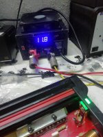
When I test an amp I normally have the power supply voltage set to 14.4 Volts. At 14.4 Volts C11 and C12 are at 18 Volts. If I lowered the voltage, C11 and C12 would also drop. When I set the Power supply to 11.8v, the voltage at C11 and C12 was ~14 volts.
I'm not sure why your only seeing 10 volts. It appears that the voltage between Pins 4 & 8 on the optocouplers is good, but low.
Did you say you have Drive and Audio?
I'm not sure why your only seeing 10 volts. It appears that the voltage between Pins 4 & 8 on the optocouplers is good, but low.
Did you say you have Drive and Audio?
If I have the drive on and check the points you have told me and I have the waveform taking horn output signal and putting the positive probe on the points of the drive, what replacement can I use to replace the optocouplers? I can't find the one that has been thinking of 6n137 here?
Optocoupler OPT100 and OPT101 HCPL2601
hcpl2601 High Speed Optocouplers | Mouser
Electronic Components Distributor - Mouser Electronics
transistor driver Q100 and Q102 MJE34o in place 2SD669
MJE340 STMicroelectronics | Mouser
Opamp U100 and U101 IR4426
IR4426PBF Infineon / IR | Mouser
hcpl2601 High Speed Optocouplers | Mouser
Electronic Components Distributor - Mouser Electronics
transistor driver Q100 and Q102 MJE34o in place 2SD669
MJE340 STMicroelectronics | Mouser
Opamp U100 and U101 IR4426
IR4426PBF Infineon / IR | Mouser
If I have the drive on and check the points you have told me and I have the waveform taking horn output signal? and putting the positive probe on the points of the drive, what replacement can I use to replace the optocouplers? I can't find the one that has been thinking of 6n137 here?
I'm not sure what you are saying here. Do you have Drive(retangular wave)? Do you have audio on the speaker terminals?
I posted links for mouser in the previous post.
I'm not sure what you are saying here. Do you have Drive(retangular wave)? Do you have audio on the speaker terminals?
I posted links for mouser in the previous post.
You mean to say "I have audio at the speaker outputs" correct?if I have audio at the speaker output, everything measures well except C11 C12 I have 10v even with 14.5v or 11v at the power input. , I have all the voltages ok apparently +90 -90 5v +12 -12
You don't need a replacement for U100 & U101. Get the HCLP2061 if you can.
If I have the drive on and check the points you have told me and I have the waveform taking horn output signal and putting the positive probe on the points of the drive, what replacement can I use to replace the optocouplers? I can't find the one that has been thinking of 6n137 here?
I don't know for sure if the 6N137 is compatable, I will look at it.
If you measure the DC voltage between Pins 5(black probe) and Pins 8(red probe on OPT100 and OPT101 what do you see? D101 and D107-1N4733 are 5volt zener diodes which set this voltage.
I'm not sure why you only see 10Vdc on C11 and C12. Varying the input voltage should vary this voltage.
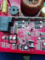
Please use locators when refering to a part, such as Q100 and Q102. This will help me and others when asking for advice.
ok opt100 and opt101 have 4v, with input power voltage 14.5v, and c12 has 12.4v and c11 has has 104v directly to the capacitor red and black tip with class d drive card installed without the card the voltage of c12 and c11 is 13.5 v with 14.5v at the input of the amplifier and one observation is that at 14.5v the mosfet transistors Q12 and Q13 of the small source get very hot
The attachment shows that the HCPL2601 and 6N37 are interchangeable, so the 6N37 should be a good replacements for OPT100 and OPT101
It's normal for the Q12 and Q13 to get warm, but I don't recall them getting hot to the touch. Changing Q100 and Q102-2SD669 or U100 and U101.
I posted links for Mouser to source the parts, Are you able to purchase them?
It's normal for the Q12 and Q13 to get warm, but I don't recall them getting hot to the touch. Changing Q100 and Q102-2SD669 or U100 and U101.
I posted links for Mouser to source the parts, Are you able to purchase them?
Attachments
- Status
- This old topic is closed. If you want to reopen this topic, contact a moderator using the "Report Post" button.
- Home
- General Interest
- Car Audio
- Kicker zx1500.1