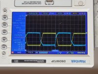
What side of the transformer are you looking at and are the blue and yellow traces from different transformers?P-P values? Frequency? More info is better.
If you don't have excessive idle current and your rails,+/-12 volts look good,this may be normal.
How did you get the power supply working?
If you don't have excessive idle current and your rails,+/-12 volts look good,this may be normal.
How did you get the power supply working?
The amp turns on and idles at 1.3. When its working correctly it was idling at 1.7. There is no switching on the output fets.
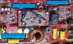
All measurements taken with my power supply at 12.4v
The positive and negative rails both sit at 106v
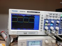
Dc across the caps is 11.15v on c6 and 14.65 on c12
+DRV 4.93 -DRV 4.93
All measurements taken with my power supply at 12.4v
The positive and negative rails both sit at 106v
Dc across the caps is 11.15v on c6 and 14.65 on c12
+DRV 4.93 -DRV 4.93
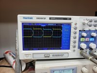
Because you have .3mv on -DRV and no waveforms on either -DRV and +DRV and there should be nothing on the SFB line something in the drive circuit has failed, or but less likely the feedback loop is open.
Check the following components:
Q100(+DRV) & Q102(-DRV)-2SD669
OPT100 & OPT101-HCPL0601N
U100 & U101-IR4426S
D100 & D106-1N5241B 11V zener
D101 & D107-1N5231B 5V zener
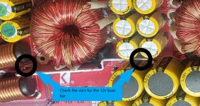
Use C11(negative side) for the +DRV reference(Black Probe)
Use C12(negative side) for the -DRV reference(Black Probe)
Check first with an ohmmeter and a DC Voltmeter at each pin of the active components
and post results
Check the following components:
Q100(+DRV) & Q102(-DRV)-2SD669
OPT100 & OPT101-HCPL0601N
U100 & U101-IR4426S
D100 & D106-1N5241B 11V zener
D101 & D107-1N5231B 5V zener
Use C11(negative side) for the +DRV reference(Black Probe)
Use C12(negative side) for the -DRV reference(Black Probe)
Check first with an ohmmeter and a DC Voltmeter at each pin of the active components
and post results
Last edited:
- Status
- This old topic is closed. If you want to reopen this topic, contact a moderator using the "Report Post" button.
- Home
- General Interest
- Car Audio
- Kicker zx1500.1