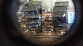
Got a diode in the power supply D34B going to the base of the driver transistors along with the drive resistors. The amp follows the SNI-4500D diagram except for these diodes. Pictures to follow, my phone and computer are not playing nice together. The markings on the diode appear to be B7.5 (the markings roll around the diode, a B, and a 7, and there is a dot, and then a 5, but it could be in any order) and I think it may be a zener, but the board does not label any other zeners as anything other than diode (D). The reason for this is I was getting no drive on that bank and found it shorted (no fets in). At first I replaced it with a 1N4148, but now that bank has about 8V drive out, and all the others have 6V drive out (the square wave looks great though). This is probably just an update to the drive that I have not seen. Any help, thanks!
The power supply fets were and will be IRFP064N. The amp had 2SC3228 and 2SA1275 drivers (died), I replaced with BD139 and BD140. The amplitude of the drive on the 3 factory diodes is 6.6V, on the one i stuck the regular diode in, 8.4v (my scope is pure analog, no fancy voltage readout). A tech I know that does a lot of these has said it should be a 1N4740 10v zener. Going to order some up. However I was told the voltages were all too high, going to compare to the other 2 amps I have that the PS did not die in. I think I need to check all the resistors etc.
The 10v zener is common. This zener limits the voltage. I don't know why they are so low. They could be 7.5v from the marking but the minimum drive is often 10v. The 10v Zeners give you about 10v of drive.
An analog scope is perfectly fine when calibrated, even at a basic level. Set your power supply to exactly 12v (use a multimeter). Set the trace to the reference line. Set coupling to DC. Set the scope to 5v/div. When you touch the probe to the the 12v supply, the trace should deflect to the 2.4 major division line.
Who told yo u that voltages were too high?
Which voltages were they referring to?
I'm lucky enough to be friends with and in some repair groups on Facebook with a great bunch of people. Shane E is a repair tech who is also the authorized warranty repair tech for a bunch of different companies. He might even be on this forum, if I find his Member name I will give him proper shout out (my77stang i think). But he was spot on, the voltages going into the drive transistors were high and the voltages going to the power supply fet gates were high when I checked the other two amps (I have three of these to repair) that still had complete factory power supplies. I will post up a good picture and proper voltages when the parts come in and I have this thing correct.
The voltages going into the base of the drive transistors, and into the gates of the PS fets. At work right now (I am considered critical Industry Infrastructure LOL). Like I said I will do a proper write up when I get parts and get it done, I know I have to replace the zeners, and most likely the 510 ohm resistors. This power supply drive is more updated than any of my schematics. So a bit more troubleshooting and testing to insure I find everything.
- Status
- This old topic is closed. If you want to reopen this topic, contact a moderator using the "Report Post" button.
- Home
- General Interest
- Car Audio
- Diode in SPL Dynamics D-7S power supply