Hi All,
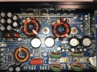
I am working on an ARC Audio XDi 805. The sub channel was damaged when the output devices GT63T40 failed.
From other posts I was able to see that ARC Audio suggested STW34NB20 as replacement. I cannot find these from reputable sources and am considering the STW40NF20 that seems very comparable.
I did reach out to ARC Audio, but have not received any response and considering the current state, am not surprised. Does anyone have any experience with these, have Service Manuals / Schematics or any other resources that may be helpful?
Particularly, I would love to know what the driver IC (U8) for the Sub Channel is?
Thanks!
Attachments
Time for an update and hopefully some advice
Hi All,
I ended up replacing the driver IC with an IR2010STRPBF. This seemed reasonable, considering that the rail voltages on this unregulated power supply is around 40-42V at 12.6V input.
I used the STW40NF20 as planned and the reason for using this was that it was quite close to the STW34NB20 mentioned by others. The Total gate charge for the STW40NF20 is 75nC, compared to the 60nC for the STW34NB20.
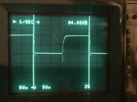
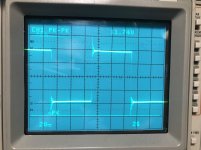
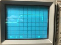
During initial testing, without any load, the sub channel worked as expected, producing clean output, but the MOSFETs did heat up a bit more than I expected. The first picture is the Gate of the High Side MOSFET, using matched probes (Gate and Source) Summed with inverted Channel B. It is hard to see, but the switching is quite close, with perhaps a tiny bit of cross conduction.
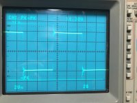
The second picture is of the low side Gate, with the probes at 1x, so a little less detail with regards to high frequency artefacts.
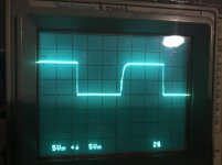
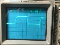
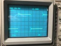
The Gate drive uses both a resistor as well as a diode for each MOSFETs. I did replace the 22ohm resistors with 30ohm resistors that reduced heating and also resulted in slightly less ringing on the output. The next two images is the rail to rail switching. 117.4V before the change and 113V with the 30ohm in place.
I ran the input voltage of the amp up to 16.5V and with the ringing, the rail to rail voltage was 147V, which I thought was still within the 200 rating of the Transistor. Keep in mind that this was without any load.
When I ran my full power test, after assembly into the heat sink, the sub channel failed after only seconds with a 4ohm load attached.
Any advice would be greatly appreciated!
Thanks!
Hi All,
I ended up replacing the driver IC with an IR2010STRPBF. This seemed reasonable, considering that the rail voltages on this unregulated power supply is around 40-42V at 12.6V input.
I used the STW40NF20 as planned and the reason for using this was that it was quite close to the STW34NB20 mentioned by others. The Total gate charge for the STW40NF20 is 75nC, compared to the 60nC for the STW34NB20.
During initial testing, without any load, the sub channel worked as expected, producing clean output, but the MOSFETs did heat up a bit more than I expected. The first picture is the Gate of the High Side MOSFET, using matched probes (Gate and Source) Summed with inverted Channel B. It is hard to see, but the switching is quite close, with perhaps a tiny bit of cross conduction.
The second picture is of the low side Gate, with the probes at 1x, so a little less detail with regards to high frequency artefacts.
The Gate drive uses both a resistor as well as a diode for each MOSFETs. I did replace the 22ohm resistors with 30ohm resistors that reduced heating and also resulted in slightly less ringing on the output. The next two images is the rail to rail switching. 117.4V before the change and 113V with the 30ohm in place.
I ran the input voltage of the amp up to 16.5V and with the ringing, the rail to rail voltage was 147V, which I thought was still within the 200 rating of the Transistor. Keep in mind that this was without any load.
When I ran my full power test, after assembly into the heat sink, the sub channel failed after only seconds with a 4ohm load attached.
Any advice would be greatly appreciated!
Thanks!
Attachments
I don't see anything (from what you posted) that should cause the outputs to fail.
I don't understand the rail-rail oscillation with 1x and 2v/div.
Thanks for using the scope in differential mode. Few people will. It was also nice to see the nice sharp display of a CRT based scope.
I don't understand the rail-rail oscillation with 1x and 2v/div.
Thanks for using the scope in differential mode. Few people will. It was also nice to see the nice sharp display of a CRT based scope.
Thanks Perry,
I forgot to mention that the 2V/div was taken with a 10x probe. It is not original Tektronics probes, so the scope does not detect the setting automatically. I also did not see anything out of the ordinary, which was why I moved on to my high power testing. I was careful moving forward, since it is quite a bit of work to assemble this amp into the heat sink.
Damage after the failure includes power supply MOSFETs, the high side output MOSFET and the IR2010. I did not check beyond that.
I guess I can try again, with IR2110S which has slightly longer Ton/Toff of 120&94 nS vs the 95&65 of the IR2010, with the much higher 500V capability and some STW46NF30, that seems like overkill to me ��.
Like always, all input appreciated!
Checking with the other two ICs would be a good next step. I've tried swapping the 2113 for the 2110 and they wouldn't always work as subs for each other, for some reason.
I don't know if you're using hot air to solder, but I wouldn't. You can control the heat on the IC much better with a soldering iron.
Don't forget about possibly having an inductor with an intermittent short.
I don't know if you're using hot air to solder, but I wouldn't. You can control the heat on the IC much better with a soldering iron.
Don't forget about possibly having an inductor with an intermittent short.
It is interesting that the 2110 would not work in stead of the 2113. On paper (datasheets) I would not have thought that to be the case, so thank you very much for that information. I will also carefully check the inductor, just in case that is the source of my problems.
I use my solder iron for removal and installation. I have a Pace ADS200 that has really good temperature control and makes removing and installing surface mount components pretty easy.
I use my solder iron for removal and installation. I have a Pace ADS200 that has really good temperature control and makes removing and installing surface mount components pretty easy.
Update Time
Hi All,
I installed an IR2110S and STW46NF30 still with the 30ohm emitter resistors and here are the wave forms that I am seeing now. Quite similar to the ones before, but the cross conduction seems less. The first two pictures are of the high side as before, but now I can see that the low side MOSFET is switching when the high side drive is below 5V as indicating by the waveform due to the captive coupling Gate Source coupling. At least that is what I believe I am seeing. Feel free to correct me if I am wrong with this.
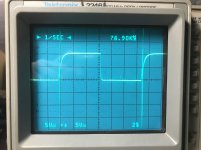
The switching frequency is a little lower @ 76.9KHz (third picture) vs the 84.85KHZ with the IR2010S.
Fourth picture is the low side gate drive. That seems fine to me also.
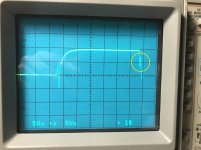
The fifth picture is the rail to rail oscillation, with a little less ringing than I had before. Again, I do not see anything of concern. With the STW46NF30's 300V rating it should not be a problem at all.
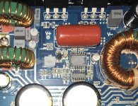
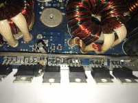
I have also included a last picture of the power supply repair that I made. That included removing carbonized PCB ares around one power supply MOSFET and using a through hole 47ohm (same value as other SMD parts) to make the connection with the gate. I did add some E6000 glue to the resistor (after the photo) to fix it in place.
Any concerns with this repair I should consider?
Thanks again for all input!
Hi All,
I installed an IR2110S and STW46NF30 still with the 30ohm emitter resistors and here are the wave forms that I am seeing now. Quite similar to the ones before, but the cross conduction seems less. The first two pictures are of the high side as before, but now I can see that the low side MOSFET is switching when the high side drive is below 5V as indicating by the waveform due to the captive coupling Gate Source coupling. At least that is what I believe I am seeing. Feel free to correct me if I am wrong with this.
The switching frequency is a little lower @ 76.9KHz (third picture) vs the 84.85KHZ with the IR2010S.
Fourth picture is the low side gate drive. That seems fine to me also.
The fifth picture is the rail to rail oscillation, with a little less ringing than I had before. Again, I do not see anything of concern. With the STW46NF30's 300V rating it should not be a problem at all.
I have also included a last picture of the power supply repair that I made. That included removing carbonized PCB ares around one power supply MOSFET and using a through hole 47ohm (same value as other SMD parts) to make the connection with the gate. I did add some E6000 glue to the resistor (after the photo) to fix it in place.
Any concerns with this repair I should consider?
Thanks again for all input!
Attachments
Last edited:
Final Summary
Hi Perry / All,
The Sub channel survived prolonged testing at a setting that induced a bit of clipping with music for > 50 min, with intermittent 4 min 40 Hz sine waves set to a maximum clean wave.
The final repair was made with:
I am sure with the IR2110S, the STW40NF20 would have worked also, based on what I saw on the scope.
Hope someone finds this helpful!
Hi Perry / All,
The Sub channel survived prolonged testing at a setting that induced a bit of clipping with music for > 50 min, with intermittent 4 min 40 Hz sine waves set to a maximum clean wave.
The final repair was made with:
- IR2110S -- High and Low Side 500V MOSFET Driver SOIC-16_300mil
- STW46NF30 -- MOSFET N-Ch 300 V 0.063 Ohm 42 A STripFET(TM)
- 30 ohm gate resistors
I am sure with the IR2110S, the STW40NF20 would have worked also, based on what I saw on the scope.
Hope someone finds this helpful!

- Status
- This old topic is closed. If you want to reopen this topic, contact a moderator using the "Report Post" button.
- Home
- General Interest
- Car Audio
- ARC Audio XDi 805 Sub Channel Driver