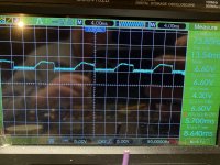
I looked at it again and it's not carrier (which would be in the 80kHz range) but it should not be there.
I wanted pins 8 and 9 shorted to eliminate the feedback from the signal and I wanted signal driven into the amp (would be seen on pins 8, 9 and 10) to see how the IC reproduced that signal. It wouldn't be clean but the output that it produced may be able to point us in the right direction.
I wanted pins 8 and 9 shorted to eliminate the feedback from the signal and I wanted signal driven into the amp (would be seen on pins 8, 9 and 10) to see how the IC reproduced that signal. It wouldn't be clean but the output that it produced may be able to point us in the right direction.
When shorting pins 8 and 9 I have no waveform on pin 10 or pin 8 or 9. I did try jumping pin 1r to pin 10 because I had audio signal there. That immediately producing a 60hz square wave. If I run a jumper wire from rca signal to pin 10 I get no waveform. With no signal and pin 8 and 9 shorted I have 6vdc on the speaker terminals
Hey perry is it possible to power the amp with the 4080 removed. I can’t seem to find this signal problem on this amp. I also can’t seem to get the dc offset control to work either.
Will removing the hip4080 break the feedback loop? Still trying to isolate why signal going to the 4080 is distorted
Will removing the hip4080 break the feedback loop? Still trying to isolate why signal going to the 4080 is distorted
Hey perry,
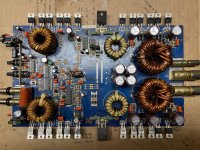
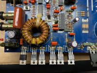
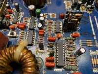
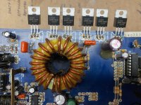
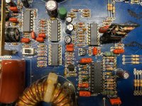
Here are the pics of the board.
Here are the pics of the board.
Attachments
-
 7A90DAC2-1BBE-436D-9898-176F76C80F16.jpg1.1 MB · Views: 44
 -
 70A5470C-63B8-400A-B99C-D601F0C3F7BA.jpg1,006.8 KB · Views: 39
 -
 641D5404-AFB8-49D8-B6CC-4E0A81FFCD8B.jpg1 MB · Views: 43
 -
 7067E555-5D95-4C51-AADB-C9C24E396A84.jpg991.2 KB · Views: 44
 -
 A31B3062-A687-413F-A23A-9881429B9EEF.jpg1.1 MB · Views: 36
That one has no pulldown resistors. You have to add one per bank. Virtually anything between a wire jumper and a 100k will generally work. Solder the resistor between the gate and source legs of the output FETs. It doesn't matter which of the 3 in each bank you solder to. 4 resistors total.
When you power up, make sure that none of the FETs are getting hot and the current draw is nothing more than normal idle.
When you power up, make sure that none of the FETs are getting hot and the current draw is nothing more than normal idle.
- Status
- This old topic is closed. If you want to reopen this topic, contact a moderator using the "Report Post" button.
- Home
- General Interest
- Car Audio
- earthquake 200dhc-mark2