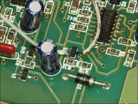
I'm looking to repair a RF 800a2 amp with one catastrophically blown channel. I believe the other channel is still working (it's been a while since I tested it & I will confirm soon). I'm reading dead shorts across all output FET outside legs on the right channel. If I'm remembering correctly and the other channel still works properly, is it safe to assume the power supply section is fine and I only need to focus on the output section of the blown channel?
I've been reading other repair threads here gathering information (and being impressed by Perry Babin's knowledge & generous willingness to help). I haven't pulled any of the FETs or source resistors yet, but from previous threads I've put together a parts list of what I see being needed so far. I'd like to know if these parts have the correct specs for the typical parts needing replaced. I've done other smaller repairs on these amps, but this is the worst one I've attempted so far.
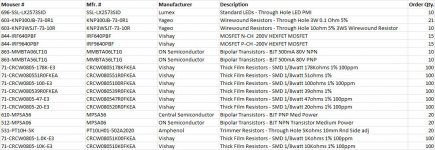
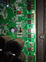
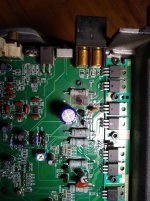
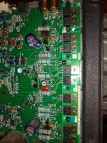
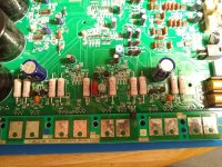
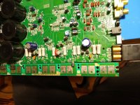
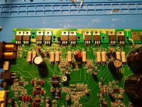
Attached are some pictures of the board and my current parts list. The quantities listed are for multiple reasons - trying to get matching date code FETs, price break cost, and for potential future use in other amps.
I've been reading other repair threads here gathering information (and being impressed by Perry Babin's knowledge & generous willingness to help). I haven't pulled any of the FETs or source resistors yet, but from previous threads I've put together a parts list of what I see being needed so far. I'd like to know if these parts have the correct specs for the typical parts needing replaced. I've done other smaller repairs on these amps, but this is the worst one I've attempted so far.
Attached are some pictures of the board and my current parts list. The quantities listed are for multiple reasons - trying to get matching date code FETs, price break cost, and for potential future use in other amps.
Attachments

Rockford didn't use wirewound resistors. You can use them but the originals are more likely metal film or metal oxide film either of which will open easier than wirewound if the outputs fail, which could save the power supply.
To get matching date codes, you'll likely have to buy about 20 unless you get lucky. If you plan on doing this work, buying 50 at a time from Arrow, Future... will (generally) ensure that you get a stick of matching (date code) FETs.
The diodes are likely all the same but I didn't look up every datasheet and look at every spec.
After you get all of the outputs and source resistors out of the circuit, you need to check every small SMD resistor in the channel, especially those in and around the outputs and source resistors.
You need to:
power this up through a current limiter when testing
initially set the bias pots fully CCW
jump the transistor as shown below
This amp is a steep learning curve. Have you done any other repairs?
Attachments
I've done other repairs to various models of the same line, but not this extensive. I'm very comfortable with soldering, but less knowledge about the circuits themselves.
Are you saying Arrow or Future will be more likely to have matching date codes than Mouser?
I know I already powered up the amp once after purchasing it as "fully working", but it obviously did not work fully (and did not blow when I used it), and it wasn't drawing excessive current when I tried it out.
Mouser has good service and a good site but not the best prices and you may not want to buy 50/100pcs of FETs from them.
When buying a full stick of TO-220 (50pcs), the distributor is likely to grab a full stick which will have the same date codes. If you buy in smaller quantities, you may get a handful of whatever is in a bin and they may have any number of date codes.
The channel was already blown out and the resistors/FETs open which is why it wasn't drawing current.
Have you replaced FETs on the MEHSA insulators before?
No, I haven't. I have a rework station with hot air as well as a fairly good older soldering gun if necessary/possible to use. I don't have any money into the amp considering I got a refund when it came totally blown, so I don't mind throwing some money at parts and experimentation on it.
The rework station will probably melt the solder.
Only use as much heat as is needed.
Keep the heat off of the board as much as possible.
Use office supply binder clips to keep the adjacent parts from coming unsoldered when working other FETs.
Work only one FET at a time (don't remove all and then try to replace the FETs).
Tin the backs of the FETs with relatively low temperature (no more than about 600F).
Rockford didn't use wirewound resistors. You can use them but the originals are more likely metal film or metal oxide film either of which will open easier than wirewound if the outputs fail, which could save the power supply.
I wasn't sure. In another thread you mentioned you use the LVR03R1000FB12 Vishay resistors, but they appear to be wirewound as well. I don't abuse my amps so maybe I don't need to worry about it? I have used these Yageo resistors recently in another amp recently and liked that they looked similar to the originals.
Attachments
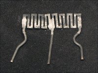
The resistors I recommended are not wirewound. They are metal strip resistors and their design is similar the the resistor below. Wirewound resistors typically have an actual metal wire wrapped around the core. They are good for surviving surges (many 10x above ratings).
Use whatever you'd like. It's not a critical issue. It's likely the least critical aspect of this repair.
Use whatever you'd like. It's not a critical issue. It's likely the least critical aspect of this repair.
Attachments
Last edited:
I see. They call them wirewound, but looking at the data sheet it's only they higher wattage that actually are.The resistors I recommended are not wirewound. They are metal strip resistors and their design is similar the the resistor below. Wirewound resistors typically have an actual metal wire wrapped around the core. They are good for surviving surges (many 10x above ratings).
Use whatever you'd like. It's not a critical issue. It's likely the least critical aspect of this repair.
I split my order up between Mouser & Future after comparing prices. I was able to order 50 each of the FETs, and will try to sell off the extras when I'm done.

Pulled all the output mosfets and went through all the resistors on the right channel. The following are open:
R340
R342
R344
R346
R347
R366
R368
R370
R372
R374
(Above were all removed before any further testing)
R328
R334
R335
R338
R362
R363
R364
R355
R357 reads 76.8k or 99.6 depending on polarity, which is similar but not exactly the same as the R257 on the left channel.
I suppose the next step will be testing diodes and transistors in these paths?
Last edited:
Hadn't had time to work on this for a while. Tonight I've replaced all the surface mount resistors that were open. All the suggested/typically blown transistors seem to test okay in diode mode, as compared to the same transistors on the other channel. Is it possible they are really okay? I bought the replacement parts, but I don't want to change them if I don't need to. Will it be safe to proceed with the source resistors & mosfets or is there a better way to test them first?
Just read this in another thread - I will go ahead and replace them all on this channel.You will also need to replace the MPSA06 and MPSA56 driver transistors. Even if they check OK, replace them. If they're leaking and you power up the amp with the new components, they will cause the outputs to fail again.
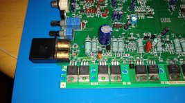
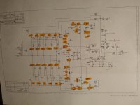
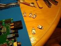
Repair is done. Replaced everything highlighted in the schematic. Soldered all the mosfets to the mehsa board with the leads loose, then temp mounted back into the heatsink and soldered a leg on each, then pulled it and finished soldering. Not super thrilled about the excess solder on the fets, but I was trying to get the heat into them quickly. They're all seated/soldered securely. Bias set to 0.05A on both channels, which ended up slightly below where they were previously set (marked the pots before I turned them counter-clockwise the first time). Everything seems to be working as it should. I'll have to give it a more thorough burn-in test another time after I refurb the heatsink.
Attachments
Perry,
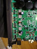
I was revisiting this amp after shelving it for a while and learning a few more things on some other repairs. I was comparing idle current draw to another amp of the same model, and while doing so reset the bias and noticed that something is strange. After setting the bias on each channel to .05A above the base current draw, if I push on the board near the right channel bias pot, the current draw will change. For instance, I end up with 1.15A draw but if I push on the board to flex it a little the draw will drop to 1.10A and sometimes even stay there after releasing pressure. Then I readjust the pot and press on the board and it might jump up in current draw. I can't tell if the pot is bad or if I have a bad connection somewhere. I can't find any bad traces or solder joints and I'm pulling my hair out trying to figure out why it's doing this. Have you seen these pots go bad?
Also, while messing with that, I noticed the TL494C is getting warm, and R5 next to it is getting warm-hot. TL494C voltage as measured from B- ground are:
PIN1: 1.963V
PIN2: 2.791V
PIN3: 68mV
PIN4: 2.4mV
PIN5: 1.542V
PIN6: 3.406V
PIN7: 1.3mV
PIN8: 19.93V
PIN9: 8.37V
PIN10: 8.37V
PIN11: 19.93V
PIN12: 19.93V
PIN13: 4.97V
PIN14: 4.97V
PIN15: 4.97V
PIN16: 1.7mV
8,11,12 seem high from other threads I found, but they also had other issues so I'm not sure. This board did fully power up and play for brief testing, but I haven't had a chance to really stress it and I'm not sure it's 100% yet.
20v is higher than normal but according to the value of the programming resistors, it's normal for this amp.
The extra solder is perfectly fine as far as I'm concerned.
Did you tin the backs of the FETs before you soldered them to the insulator?
The leads are better formed on a radius than a sharp bend.
If you tin the FETs (no hotter than about 650F) and form the leads, then place the FETs (insulator clamped and board with at least 2 screws) and solder the center leg, then you can pull the board and solder the rest of the legs.
R5 and R6 should be heating equally and the heating is caused by the high regulator voltage.
- Status
- This old topic is closed. If you want to reopen this topic, contact a moderator using the "Report Post" button.
- Home
- General Interest
- Car Audio
- Rockford Fosgate 800a2 repair