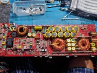
Ok so im back to looking at these amplifiers again. Since i cant remember what i have and havent done. Im starting at the power supply. Right now i only have four ps misfet in circuit.
I beleive there is a problem with the voltage regulation.
main ground to class control board. measurement are 15.32
-16.43vdc
4.97
What should i measure at q21-q23
I beleive there is a problem with the voltage regulation.
main ground to class control board. measurement are 15.32
-16.43vdc
4.97
What should i measure at q21-q23
Attachments
Q21 (15v) Q22 (-15v) Q23 (5v) so it appears the power supply and regulator circuit are working. If memory serves the +/- rails should be about 110 volts.
If the rectifier diodes are not shorted, reinstall them and replace, same with the output mosfets.
What are the symptoms? Protection, no Drive no Output?
If the rectifier diodes are not shorted, reinstall them and replace, same with the output mosfets.
What are the symptoms? Protection, no Drive no Output?
Check U3-74HC74 Pins 4 & 6 for 5Vdc from neg speaker terminal. If no 5Vdc on Pin 6 Look at Q9,18,19,20-KTC4401 for shorted devices. Also, check Q101-MPSA92 and Q111-MPSA42. Q101 and Q111 are the OCP sensors and tie back the U3 through the KTC4401 transistors. If any short whichs has been known to happen they will send a false and cause amp to go into protection mode.
Okay, Look at the DC voltage across C11 and C12. You should have about 18 volts.
This is the isolated supply for the Class D drivers Q102 associated with C12 and Q100 associated with C11.
Check the Voltages at all three legs of Q102 and Q100 using the negative side of their associated capacitors.
Recheck the following. I'm not clear if you replaced the devices. There should be 5 volts on U3-Pins 4 & 6. You may need to replace the 74HC74 or the OPT1-PC817- You should be using the negative speaker terminal as a reference or the power transformer secondary.
Q9,18,19,20-KTC4401 and Q101-MPSA92 and Q111-MPSA42
ok so across the capacitors 15.69vdc
i changed the 74hc74d and now have
pin 4) 4.979v
pin 6) 4.726v
the protection stopped somehow? Not right away after changing the 74hc74d but a few power up after.
the three legs from the green caps in front of them leg 1 (left)
q111
1) 0.00
2) 0.00
3) 128.6
q101
1) 0.00
2) 0.00
3) -130.6
i changed the 74hc74d and now have
pin 4) 4.979v
pin 6) 4.726v
the protection stopped somehow? Not right away after changing the 74hc74d but a few power up after.
the three legs from the green caps in front of them leg 1 (left)
q111
1) 0.00
2) 0.00
3) 128.6
q101
1) 0.00
2) 0.00
3) -130.6
Last edited:
So the 74HC74 was bad and replacing it restored the protection circuit. Pin 6 of U3 is the Not Q output of the flip flop and when low will cause Pin 16 of U2-TL594 to go high and causing a Protection condition.
Now that the amp is out of protection what is the status of output, drive etc..
Now that the amp is out of protection what is the status of output, drive etc..
Last edited:
When you say something is pulling down the voltage to 10.2 vdc,which voltage are you referring to?
And without the class D board the amp Powers up and all voltages appear to be nominal?
Please give as much detail as possible. This amp is tricky, with isolated supply's and the class D board complicates troubleshooting.
And without the class D board the amp Powers up and all voltages appear to be nominal?
Please give as much detail as possible. This amp is tricky, with isolated supply's and the class D board complicates troubleshooting.
- Status
- This old topic is closed. If you want to reopen this topic, contact a moderator using the "Report Post" button.
- Home
- General Interest
- Car Audio
- Kicker ZX1500.1 Help.
