The voltages on Q303/304 have changed.
With the voltmeter, black probe on amp ground:
Q303. Q304
Emitter -3.60 -3.62
Base -4.19 -4.20
Collector -46.31 -46.62
With the voltmeter, black probe on the negative rail:
Q303 Q304
Emitter 52.81 52.79
Base. 52.21 52.20
Collector 10.10. 9.76
I changed the 2n5401 transistors to try a fresh pair. After seeing the different voltages, I reconnected D305-308 and reattached pin1 of IC304 and IC306 in an effort to try to restore the previous readings. I will detach those connections again if you say that is necessary. I am trying to avoid getting to the point where I start to tear apart a good amp because I don't know what I am doing...
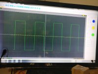
So, the only difference is having D307 and D308 back in the circuit and that's what gave you the square wave?
If you're not sure what gave you the square wave, step back until you find what it was.
I didn't know D305/6 were out. They protect the input of the inverter from excessive voltage.
If you're not sure what gave you the square wave, step back until you find what it was.
I didn't know D305/6 were out. They protect the input of the inverter from excessive voltage.
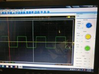
The square wave on Q303/304 collectors was only there when R316/317 were removed. It also removed the drive and supply voltage from the transistor so I assumed the square wave was just bleeding through, so I put fresh transistors. That was the only time I have seen a square wave on Q303/304 collectors.
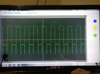
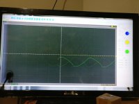
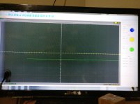
This is with the 100hz sine wave playing at volume 10. Speaker connected and audible output sound. Not seeing any square wave here. Have the rail to rail oscillation on the outputs though.
PDX1.600. Q3304
Leg1
Leg2
Leg3
PDX1.600. Q3304
Leg1
Leg2
Leg3
Attachments
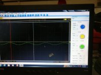
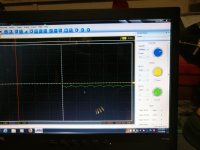
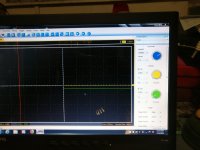
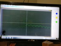
In the PDX600, I see a square wave on one end of R3003 and R3009 with a sawtooth waveform on the other end. IC3001 also has a waveform on pin1 and pin6 in the 600, but in the 1000, IC301 and IC302 have a square wave on pin6 when the signal volume is raised and have no waveforms on any other pin.
Attachments
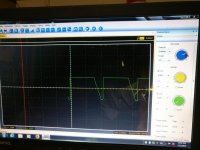
I need some guidance as to what I am looking for in the PDX1.600. The amp is functional and playing but there is no square wave present on the level shifting transistor. I see square, sawtooth, and sine waves in the preamp section on various resistors and components.
Is it that the PDX1.1000 operates differently by utilizing a square wave on the level shifting transistor, or is it supposed to look like the PDX1.600?
I also can see different output from the NJM ICs that feed the level shifting transistor. If I am supposed to scope the 600 in an effort to learn where the 1000 goes wrong, I understand that process, even if I don't understand the scientific proceeds that achieves that...
- Status
- This old topic is closed. If you want to reopen this topic, contact a moderator using the "Report Post" button.
- Home
- General Interest
- Car Audio
- Alpine PDX1.1000 powers on, no audio (IR2010s HELP)