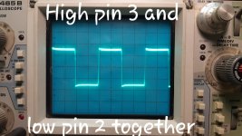
Before I hit the add button after having both ch 1 and ch2 on (shows as a single trace till added to 12v), I just get that extra trace that shows once I hit add.. The one deflects up and brings that extra line with it, other deflects down but brings the extra line with it, and both together one line goes up, one goes down, and that other trace sits there. Pics are in #59
On virtually all scopes, both have to be enabled. This scope is an oddity.
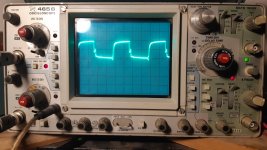
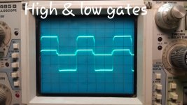
Yes, that's about what you should see in any of the outputs as well as the power supply FETs.
When starting to use the scope like this, it's sometimes best to put both probes on the drain of an FET and adjust the var control for one trace to get the trace as flat as possible.
I'm assuming that you calibrated both probes, previously/individually on the scope's test signal.
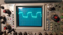
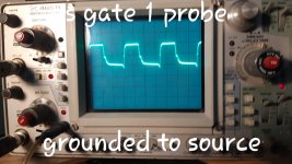
Yes. I had to make the lines as flat as possible. Both needed a bit of adjustment.
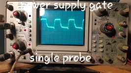
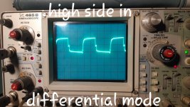
I just did as you said put both on the drain. I get no deflection. Unless I adjust the var too much. Otherwise, I did turn it a bit to get the line as fine as possible. This is the new pic from high side
I just did as you said put both on the drain. I get no deflection. Unless I adjust the var too much. Otherwise, I did turn it a bit to get the line as fine as possible. This is the new pic from high side
Attachments
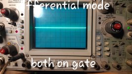
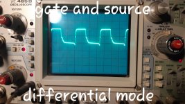
It's def cool. ...was I suppose to get nothing when in differential mode with both probes on gate? I assume cause they are a mirror of each other it stays flat?
Attachments
Last edited:
You don't put both on the same terminal unless you're trying to get the trace straight. You place one probe on the source and one on the gate. This makes your meter act like a multimeter with a graphic display. You wouldn't place both meter probes on the same point if you were measuring the voltage.
")

For the POWER SUPPLY (not the outputs), if you ground your scope probe to the source leg of the FET, you will get a cleaner signal. Don't allow the ground clip to short to the drain. Using something like the last image on Tech Tips 10, item 17 is safer than touching with the clip.
As a side note, when in differential mode, if you connect the two scope probe ground clips together, it will sometimes give a cleaner signal.
As a side note, when in differential mode, if you connect the two scope probe ground clips together, it will sometimes give a cleaner signal.
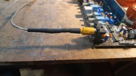
Nice. I really should make up some more ground things that connect directly to the probe. I made this a bit back too. So I can connect scope directly to secondary ground. Just removed the middle pin. Removed the middle wire. Ran wire from ground shield to scope. Seems to do the job.
Attachments
Last edited:
On larger amps, the RCA shield isn't always connected to the secondary ground. If it is it's often through a relatively high value resistor.
If the secondary ground isn't connected to the primary ground and a speaker wire shorts to ground, it essentially sends the speaker level output back through the RCA shields. The RCA ground, even if through a relatively high resistance may be OK but the primary ground should be as good since the primary and secondary are generally tied together with a RC network.
For many large amps, the negative speaker terminal is a good point to connect to the secondary ground. Use your meter to confirm that the -sp is connected to the secondary ground before using it.
- Status
- This old topic is closed. If you want to reopen this topic, contact a moderator using the "Report Post" button.
- Home
- General Interest
- Car Audio
- American Bass 1100.1